VOGONS


First post, by rkurbatov

User metadata
Rank Member
Rank
Member

There is a Socket 7 motherboard with strange connector sold on our local auction site. The image quality is crappy, I cannot see even the type of the chipset (except for being intel) but socket is definitely Socket 7 with P90 CPU installed in it.

image;s=1000x700

The connector is between CPU and voltage regulator. May be somebody can recognise it? And the board?

486: ECS UM486 VLB, 256kb cache, i486 DX2/66, 8MB RAM, Trident TGUI9440AGi VLB 1MB, Pro Audio Spectrum 16, FDD 3.5, ZIP 100 ATA
PII: Asus P2B, Pentium II 400MHz, 512MB RAM, Trident 9750 AGP 4MB, Voodoo2 SLI, MonsterSound MX300

Reply 1 of 15, by PcBytes

User metadata
Rank Oldbie
Rank
Oldbie

Looks like a Epox judging by the BIOS "C" sticker (they were about the only to stick that shiny sticker on their BIOS chips.) and the chipset is a 430FX. The connector you're seeing inbetween the CPU and voltage regulator is a VRM module socket for using dual voltage Pentium MMX chips on those boards.

Edit: Found it - EPoX EP-P55-IT.
https://theretroweb.com/motherboards/s/epox-pronix-ep-p55-it

"Enter at your own peril, past the bolted door..."
Main PC: i5 3470, GB B75M-D3H, 16GB RAM, 2x1TB
98SE : P3 650, Soyo SY-6BA+IV, 384MB RAM, 80GB

Reply 2 of 15, by mkarcher

User metadata
Rank l33t
Rank
l33t

That board as is supports socket 5 CPUs only. It only has one voltage regulator, dropping 5V to 3.3V. For split-voltage CPUs, you need a second voltage regulator, which could be installed left to the 3.3V regulator, or inserted as a plug-in VRM (voltage reduction module). The slot you ask about is the VRM connector, called "header 7" by Intel. See http://intel-vintage-developer.eu5.org/DESIGN … TS/24318701.PDF page 29.

Reply 3 of 15, by rkurbatov

User metadata
Rank Member
Rank
Member

Thank you, guys, that was quick 😀

That's why I love PCs of that era - so many standards and companies, so many unknown stuff.

486: ECS UM486 VLB, 256kb cache, i486 DX2/66, 8MB RAM, Trident TGUI9440AGi VLB 1MB, Pro Audio Spectrum 16, FDD 3.5, ZIP 100 ATA
PII: Asus P2B, Pentium II 400MHz, 512MB RAM, Trident 9750 AGP 4MB, Voodoo2 SLI, MonsterSound MX300

Reply 4 of 15, by Sphere478

User metadata
Rank l33t++
Rank
l33t++

Re: IBM Personal Computer 365 / M/T: 6589-17U / Voltage Regulator Module (VRM)

It’s the vcc2 voltage regulator module.

Sphere's PCB projects.
-
Sphere’s socket 5/7 cpu collection.
-
SUCCESSFUL K6-2+ to K6-3+ Full Cache Enable Mod
-
Tyan S1564S to S1564D single to dual processor conversion (also s1563 and s1562)

Reply 6 of 15, by Sphere478

User metadata
Rank l33t++
Rank
l33t++

Yes

But a single plane cpu will also jumper vcc2 and vcc3 all by its self as it doesn’t separate them.

Sphere's PCB projects.
-
Sphere’s socket 5/7 cpu collection.
-
SUCCESSFUL K6-2+ to K6-3+ Full Cache Enable Mod
-
Tyan S1564S to S1564D single to dual processor conversion (also s1563 and s1562)

Reply 7 of 15, by Horun

User metadata
Rank l33t++
Rank
l33t++

Exactly Sphere478 !! Most VRM socketed boards do need jumpers or a "shorting block" AKA "dummy" VRM to short pins for STD (non-MMX) Pentium cpu's.
Here are pics of a VRM types and where to put jumpers if you do not have one. Also a pic of my Intel Advanced ATX with jumpers and a P-90.
Note only standard Pentiums will work this way as long as there is a Vreg on board that can be set for 3.3v/3.45v. Your board has a Vreg so should be OK.
Be very careful as how you jump those pins in the VRM socket. If you count wrong/jump wrong could be a bad thing ;p
Hope it helps....
edit: sorry the first Intel doc page was too small to read proper...

Attachments

Hate posting a reply and then have to edit it because it made no sense 😁 First computer was an IBM 3270 workstation with CGA monitor. Stuff: https://archive.org/details/@horun

Reply 8 of 15, by Sphere478

User metadata
Rank l33t++
Rank
l33t++

I just noticed your unusual ram config also. 🤔

Using not only mis matched in the upper bank but single sided and double sided. This may cause issues. (Or may work.. test and see, but I would never do that. Might be glitchy)

Note about that board, it looks like it has smd and dip cache? Or is that onboard memory? That’s weird to see a coast, dip and smd sram all on one board. Truly an odity.

Sphere's PCB projects.
-
Sphere’s socket 5/7 cpu collection.
-
SUCCESSFUL K6-2+ to K6-3+ Full Cache Enable Mod
-
Tyan S1564S to S1564D single to dual processor conversion (also s1563 and s1562)

Reply 9 of 15, by majestyk

User metadata
Rank Oldbie
Rank
Oldbie
Sphere478 wrote on 2022-09-20, 05:05:

Note about that board, it looks like it has smd and dip cache? Or is that onboard memory? That’s weird to see a coast, dip and smd sram all on one board. Truly an odity.

The two square chips are Intel cache controllers.

Something like this:
https://www.datasheets360.com/pdf/1516513542054671340

Reply 10 of 15, by Sphere478

User metadata
Rank l33t++
Rank
l33t++

Ah, that makes sense then. Thanks. 😀

Sphere's PCB projects.
-
Sphere’s socket 5/7 cpu collection.
-
SUCCESSFUL K6-2+ to K6-3+ Full Cache Enable Mod
-
Tyan S1564S to S1564D single to dual processor conversion (also s1563 and s1562)

Reply 11 of 15, by mkarcher

User metadata
Rank l33t
Rank
l33t
Sphere478 wrote on 2022-09-20, 05:05:

Note about that board, it looks like it has smd and dip cache? Or is that onboard memory? That’s weird to see a coast, dip and smd sram all on one board. Truly an odity.

Looks like this is a dual-bank configuration (makes a lot of sense when you use asynchronous cache, because interleaving the banks allows for higher burst rates). The primary bank is soldered on board, using the rectangular SMD chips. The Pentium has a 64-bit frontside bus, and those are 32-bit chips, so two of them make a bank. The second bank is optional, and can be added either as DIP chips (they are 8 bits per chip, so eight of them make a bank) or a COAST module (provides 64 bits). As bank interleaving requires two identically sized banks, I am confused that the board has 32-pin sockets and 28-pin RAMs inserted. If the onboard cache is 256KB (32kBit * 64), you need 256kBit chips to add a second bank which always come in DIP28 case. If the onboard cache is 512KB (64kBit * 64), you need 512kBit chips to add a second bank, which always come in DIP32 case. So I guess there are variants of the board with 256KB and 512KB onboard cache, and the manufacturer didn't bother putting different sockets on the different variants.

EDIT: This is wrong. The SMD chips are data buffer chips, not cache chips. majestyk got that (mostly) right.

Last edited by mkarcher on 2023-06-07, 19:38. Edited 1 time in total.

Reply 12 of 15, by Sphere478

User metadata
Rank l33t++
Rank
l33t++

I think majestyk is correct about them being cache controllers.

Sphere's PCB projects.
-
Sphere’s socket 5/7 cpu collection.
-
SUCCESSFUL K6-2+ to K6-3+ Full Cache Enable Mod
-
Tyan S1564S to S1564D single to dual processor conversion (also s1563 and s1562)

Reply 13 of 15, by majestyk

User metadata
Rank Oldbie
Rank
Oldbie

Assuming this is an Intel 430FX board, the typical setup should be like this:

fx_setup.jpeg
Filename
fx_setup.jpeg
File size
208.88 KiB
Views
659 views
File license
Public domain

The two QFP-chips are Intel cache controllers and I always considered them part of the chipset.
The positioning on the Epox board is a bit unusual, though.

Reply 14 of 15, by rkurbatov

User metadata
Rank Member
Rank
Member

Thanks Necroware, we have a shiny new VRM module that can be used to upgrade such mobos.

And I just bought a new one from PCChips with Opti Viper chipsets onboard. Just tired of intel chipsets and want something different. Will try different CPUs once VRM board comes from PCBWay.

486: ECS UM486 VLB, 256kb cache, i486 DX2/66, 8MB RAM, Trident TGUI9440AGi VLB 1MB, Pro Audio Spectrum 16, FDD 3.5, ZIP 100 ATA
PII: Asus P2B, Pentium II 400MHz, 512MB RAM, Trident 9750 AGP 4MB, Voodoo2 SLI, MonsterSound MX300

Reply 15 of 15, by mkarcher

User metadata
Rank l33t
Rank
l33t

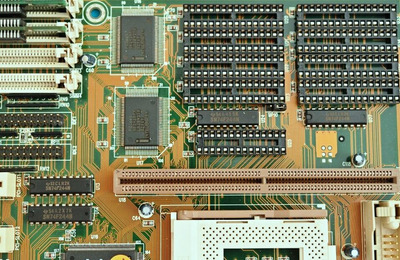
majestyk is right: These chips are not 32-bit async cache chips, as I claimed, but they are part of the three-chip north bridge. The north bridge on the 430FX chipset consists of one 82437FX chip that contains all the control logic and deals with addressing, whereas the data itself is routed through the two 82438FX chips. These chips connect to 32 data bits of the processor, 32 data bits of the RAM and 8 data bits for the PCI host interface each. Both chips combined result in a 64bit/66MHz interface to the processor, a 64-bit interface to the RAM and a 16bit/66MHz interface to the PCI host logic. The PCI host logic then obviously translates this to 32bit/33MHz. These chips are not involved when accessing the L2 cache: The data lines of the L2 cache are directly connected to the frontside bus, so transfers between the Pentium Processor and the L2 cache are performed by the 82437FX without assistance from the 83438FX chips.

In the datasheet, the 82437FX is called "System Controller" which is abbreviated as "TSC", whereas the 82438FX is called "Data Path" which is abbreviated as "TDP". The letter "T" is not explained, but it might be related to the code name "Triton" of the 430FX chipset. The reason the north bridge is split into three chips is that the 430FX uses QFP chips. The 82437FX is in the biggest QFP package available, it has 208 pins. This is just not enough pins to deal with a 64-bit FSB that is decoupled from a 64-bit memory data bus (this requires 128 pins, which is more than half of the pin count of a QFP208), so the north bridge function had to be split into multiple chips. The 430HX approached this challenge in a different way: The north bridge of that chipset is a BGA chip.