VOGONS


First post, by anetanel

User metadata
Rank Member
Rank
Member

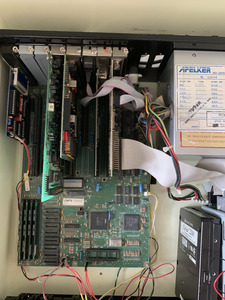
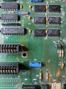
I have a 286 motherboard, running the CHIPS & Technologies 82C235 chipset.
(Help identifying a 286 motherboard)

I found it to be 99% identical to this board:
https://theretroweb.com/motherboards/s/dtk-tech-1636

When I got it, I used an external Tadiran battery (3.6v) and it worked fine for a while, but now it is always giving this error on boot:
"Real time clock error"

If I enter the BIOS/SETUP I can set the time, but when exiting and resetting it always give the error.
When entering the BIOS again, the time shown is the same as I entered, no matter how much time has passed.

What I tried so far:

  • Verified with a multimeter that the battery gives 3.6v.
  • Replace the battery with an identical one.
  • Replaced the battery with a 3xAA pack, that measures about 4.8v.
  • Reset the CMOS with debug command:
    debug
    o 70 2E
    o 71 FF
    quit

Nothing so far helped.

Occasionally when I mess with the battery I get another message, something like: "System battery is dead. Replace and run SETUP". Though I'm not able to consistently replicate this, and after setting the time it goes back to give the same "Real time clock error" error.

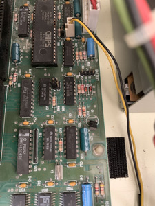
Unlike the DTK TECH-1636 motherboard, mine does not have an internal battery option, and the 3-pin W7 jumper that supposed to switch between internal and external battery, is a 4-pin grid, where pins 2&4 are shorted internally, pin 1 in connected to the battery connector pin 1 (which is the hot wire), and pin 3 is going to the d2 diode. Not sure what to make of it.
The battery used to work without me changing anything in that jumper (It had a jumper between 2-4 which are connected anyway).

Searching the forum I found some similar errors, but as far as I can tell they were all related to the dreaded DALLAS chip, which I don't have on my board (right? am I missing it?)

Any help is appreciated 😀

Attachments

  • IMG_7010.jpg
    Filename
    IMG_7010.jpg
    File size
    1.04 MiB
    Views
    1015 views
    File license
    Public domain

Reply 1 of 17, by quicknick

User metadata
Rank Oldbie
Rank
Oldbie

Does the clock advance while you're in BIOS setup? If not, the crystal (I'm assuming Y2, 32.768kHz) might be bad. Had this happen at least once.

[edited mistake, should be 32.768kHz or 32768Hz]

Last edited by quicknick on 2022-10-03, 21:34. Edited 1 time in total.

Reply 2 of 17, by anetanel

User metadata
Rank Member
Rank
Member
quicknick wrote on 2022-10-03, 11:32:

Does the clock advance while you're in BIOS setup? If not, the crystal (I'm assuming Y2, 32768kHz) might be bad. Had this happen at least once.

It does not. Interesting.
It does advance in DOS though.. I guess it is not the same.
How can i check the crystal? With oscilloscope? I have only a multimeter right now. And a logic analyzer that i never even opened 😝

Reply 3 of 17, by quicknick

User metadata
Rank Oldbie
Rank
Oldbie

I think you need an oscilloscope for that, or if your multimeter can also measure frequency it could work.
But 32.768kHz "clock crystals" are abundant and cheap, you could just replace it.

Reply 4 of 17, by rasz_pl

User metadata
Rank l33t
Rank
l33t

you need high impedance probe to measure crystal signal directly, so clean U26 to see the markings, look at the datasheet and measure on the output of whatever 74 series chip circuit implemented there. Also check if the C50 cap is all right. Or just replace blind 😀

and hole hell, take that motherboard out of the case and wash it 😀

Open Source AT&T Globalyst/NCR/FIC 486-GAC-2 proprietary Cache Module reproduction

Reply 5 of 17, by anetanel

User metadata
Rank Member
Rank
Member
rasz_pl wrote on 2022-10-04, 04:06:

you need high impedance probe to measure crystal signal directly, so clean U26 to see the markings, look at the datasheet and measure on the output of whatever 74 series chip circuit implemented there. Also check if the C50 cap is all right. Or just replace blind 😀

and hole hell, take that motherboard out of the case and wash it 😀

The chip is a MC14069UBCP - an hex inverter, and this is its datasheet:
https://pdf1.alldatasheet.com/datasheet-pdf/v … C14069UBCP.html

Capture.PNG
Filename
Capture.PNG
File size
30.85 KiB
Views
908 views
File license
Public domain

I see that the crystal is connected to pin 6 (OUT3) and I get continuity to pin 13(IN 6) as well.. it is normal?
The other leg of the crystal is connected to C50 which is connected to pin 11 of U26 (IN 5) on its other side. The capacitor is not short, so... good?

IMG_7022.jpg
Filename
IMG_7022.jpg
File size
433.2 KiB
Views
908 views
File license
Public domain

In any case, I don't have an Oscilloscope yet, so I cant test it. I ordered crystals, so at least I'll be able to replace it when they arrive.

BTW, since the time I took the pictures a few years ago, I cleaned the mother board as much as I could and even repainted the case.. I think it looks as good as it can right now 😀

IMG_7020.jpg
Filename
IMG_7020.jpg
File size
389.84 KiB
Views
908 views
File license
Public domain

Reply 6 of 17, by rasz_pl

User metadata
Rank l33t
Rank
l33t
anetanel wrote on 2022-10-04, 08:21:

I see that the crystal is connected to pin 6 (OUT3) and I get continuity to pin 13(IN 6) as well.. it is normal?
The other leg of the crystal is connected to C50 which is connected to pin 11 of U26 (IN 5) on its other side. The capacitor is not short, so... good?
IMG_7022.jpg

similar circuit https://minuszerodegrees.net/images2/5170_bat … y_circuitry.jpg

Open Source AT&T Globalyst/NCR/FIC 486-GAC-2 proprietary Cache Module reproduction

Reply 8 of 17, by anetanel

User metadata
Rank Member
Rank
Member

I think I figured the probe placement. I measured pins 11 and 10 of the IC, and got a nice sine wave of about 32.7 Khz at the input, and square wave at the output.
I guess that means that the crystal is good?

Attachments

  • IMG_7051.jpg
    Filename
    IMG_7051.jpg
    File size
    1.09 MiB
    Views
    846 views
    File license
    Public domain
  • IMG_7052.jpg
    Filename
    IMG_7052.jpg
    File size
    974.21 KiB
    Views
    846 views
    File license
    Public domain

Reply 10 of 17, by anetanel

User metadata
Rank Member
Rank
Member
rasz_pl wrote on 2022-10-13, 17:04:

trace where the clock is going

When compared to the diagram of the 5170 that you posted earlier, it is very similar but not exactly the same.
I replaced the pin numbers I was able to identify in the diagram.
The main two differences I spotted are:
1. The output at pin 6 is connected to the input of pin 13
2. I could not find anything that is connected in parallel to the input of pin 5.
Also, the 2 unused pins (3 and 5 in the 5170) are chained, instead of both pulled low.

Here is what I was able to draw.. sorry :\

Attachments

  • IMG_7055.jpg
    Filename
    IMG_7055.jpg
    File size
    473.39 KiB
    Views
    822 views
    File license
    Public domain
  • IMG_7054.jpg
    Filename
    IMG_7054.jpg
    File size
    224.54 KiB
    Views
    822 views
    File license
    Public domain

Reply 13 of 17, by rasz_pl

User metadata
Rank l33t
Rank
l33t
anetanel wrote on 2022-10-13, 18:41:

What cd4069? Did you mean mc14069?

same chip
pin 10, or 12, look at all the inverter outputs for any traces going to CHIPS SCAT 82c235 pin 140 https://www.datasheetarchive.com/pdf/download … =O&term=f82c235 page 53

or just use scope on pin 140

Open Source AT&T Globalyst/NCR/FIC 486-GAC-2 proprietary Cache Module reproduction

Reply 14 of 17, by anetanel

User metadata
Rank Member
Rank
Member

I think I found the issue.
I had to take the board out and carefully examine it from both sides under hard light.
output pin 12 is connected to input pin9, and the output pin 8 is connected by several vias to the 28c23g chip.
The problem is that one trace is broken due to corrosion (marked by the red arrow) 🙁
I guess I'll need to get some thin bodge wires and start soldering.

I need to invest in quality sharp probes for my multimeter... I had to improvise by connecting the probe to tweezers with an alligator clip 😜

Attachments

  • IMG_7057.jpg
    Filename
    IMG_7057.jpg
    File size
    713.15 KiB
    Views
    774 views
    File license
    Public domain

Reply 15 of 17, by rasz_pl

User metadata
Rank l33t
Rank
l33t

You can _slightly_ sharpen the tip depending on quality of the probes (thickness of nickel plating over copper core).
You could use this opportunity and put motherboard in a bathtub with washing powder/dishwasher, use old toothbrush to clean all nooks an crannies, rinse well, then hair drier to push water from under chips/sockets and dry for a day near the radiator. Will let you see better other potential corroded spots.
No need for bodge wire for this one, scrape soldermask with a bit of soft sandpaper and tin the trace. Solder should patch it up on its own.

Open Source AT&T Globalyst/NCR/FIC 486-GAC-2 proprietary Cache Module reproduction

Reply 16 of 17, by anetanel

User metadata
Rank Member
Rank
Member

It is alive! 😀 😀
For the life of me, I was not able to bridge the gap with solder only. There was no trace copper underneath to grab it.
After more than an hour of trying, fearing I'll do more damage to the board, I cut my losses and bodged it on the back. Connected pin 8 of the IC to one of the vias after the broken trace.
Powered the board and... No more error! And the clock progresses in BIOS too!
I may replace the wire with an appropriate gauge later. All I had was pretty large, so I had to solder single stand...
Many many thanks @rasz_pl and @quicknick!!

Attachments

  • IMG_7063.jpg
    Filename
    IMG_7063.jpg
    File size
    406.33 KiB
    Views
    733 views
    File license
    Public domain