Reply 20 of 60, by nathanieltolbert
Rank
Member
More pictures
More pictures
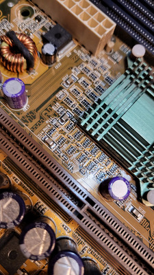
This thing is filthy!
You will have to do some serious cleaning *before* you proceed. Especially the area between the green nothbridge heatsink and the RAM slots. The heatsink needs to be removed for cleaning, fresh thermal compound is a must.
majestyk wrote on 2022-10-21, 19:25:This thing is filthy!
You will have to do some serious cleaning *before* you proceed. Especially the area between the green nothbridge heatsink and the RAM slots. The heatsink needs to be removed for cleaning, fresh thermal compound is a must.
really? Apparently people around here really don't take care of their hardware. This is fairly clean. The sockets didn't have any buildup of dust in them, and thankfully the board isn't covered in that awful tar dust that you get with cigarette smokers.
Could you inspect te board with a magnifying glass to check if there are some obvious cuts on traces?
Time and effort yields eventually.
If it beeps it speaks, just gotta figure out the language 😀
Ok, enough pep $hit.
PC#1 Pentium 233 MMX - 98SE
PC#2 PIII-1Ghz - 98SE/W2K
Nexxen wrote on 2022-10-21, 20:32:Could you inspect te board with a magnifying glass to check if there are some obvious cuts on traces? Time and effort yields eve […]
Could you inspect te board with a magnifying glass to check if there are some obvious cuts on traces?
Time and effort yields eventually.
If it beeps it speaks, just gotta figure out the language 😀Ok, enough pep $hit.
Okay I have taken a look with the small magnifying glass that came with my helping hands. I can't see anything. It is quite possible that my eyes just aren't good enough to see anything. I will talk to my friend tomorrow and see if I can borrow his jewelers lenses he uses while painting that have lighting and magnification. I removed the offensive dust and popped off the heatsink for the northbridge. The thermal paste was tacky, but not liquid like. I cleaned it with some 95% iso and a soft bristle tooth brush I use for cleaning things. I applied what thermal paste I have which is thermal Grizzly. What is the next step that is recommended to do in continuation of diagnosing the 8 beeps?
easy way - another cpu or cpu tested in another board
hard way - logic analyzer on ISA bus and seeing what is going on 😀
POST card wont help much, will show stopping around 2C-30
nathanieltolbert wrote on 2022-10-21, 04:37:Okay, the JETKey says Fastest Keyboard BIOS on the chip. So I thought maybe it would be something I could burn like any other BIOS chip.
Huh ? Thanks majestyk your comment got me thinking. There should not be a specific external Keyboard controller chip on the board. That is built into the VIA VT82c686 south bridge chip.
The 32 pin socket is for a BIOS eeprom, I just pulled the sticker off my K7M v1.04 and is a SST39SF020 (2Mb bit) .
If someone put a KBC IC in that socket that could be part of the problem ;p
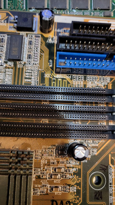
Can you post a picture of the whole board ? or at least the area around the BIOS chip and battery ?
Hate posting a reply and then have to edit it because it made no sense 😁 First computer was an IBM 3270 workstation with CGA monitor. Stuff: https://archive.org/details/@horun
Horun wrote on 2022-10-22, 03:13:Huh ? Thanks majestyk your comment got me thinking. There should not be a specific external Keyboard controller chip on the boa […]
nathanieltolbert wrote on 2022-10-21, 04:37:Okay, the JETKey says Fastest Keyboard BIOS on the chip. So I thought maybe it would be something I could burn like any other BIOS chip.
Huh ? Thanks majestyk your comment got me thinking. There should not be a specific external Keyboard controller chip on the board. That is built into the VIA VT82c686 south bridge chip.
The 32 pin socket is for a BIOS eeprom, I just pulled the sticker off my K7M v1.04 and is a SST39SF020 (2Mb bit) .
If someone put a KBC IC in that socket that could be part of the problem ;p
Can you post a picture of the whole board ? or at least the area around the BIOS chip and battery ?
Sorry, I was referencing an issue I was having with another board. Thankfully with everyone's help on here I got that one working. Sorry, I tend to go on tangents when I am working on multiple issues and multiple products at once.
rasz_pl wrote on 2022-10-22, 02:59:easy way - another cpu or cpu tested in another board
hard way - logic analyzer on ISA bus and seeing what is going on 😀
POST card wont help much, will show stopping around 2C-30
I do have another motherboard that was supposed to be here today, but it required a signature, and I wasn't here. So I will pick it up tomorrow. Then I can test the CPU.
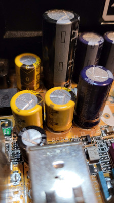
I cant tell for sure from these pictures as it could be a trick of the light but is there corrosion in the area circled like from a leaking cap?

Plus it could be a trick of light and shadow but are the circled caps slightly bulged?

Nah, those caps look beautiful. They can still be bad, but you couldnt tell by looking at them.
Grem Five wrote on 2022-10-22, 04:07:I cant tell for sure from these pictures as it could be a trick of the light but is there corrosion in the area circled like fro […]
I cant tell for sure from these pictures as it could be a trick of the light but is there corrosion in the area circled like from a leaking cap?
Plus it could be a trick of light and shadow but are the circled caps slightly bulged?
In the first photo it could be a build up of dust. It's hard to tell because I did clean the board lightly with 95% IPA and a soft bristle toothbrush after the pictures were taken. The cap appears fine upon visual inspection. But it does look a little expanded in the picture. I'm not sure what is happening there. Possibly a trick of the lens?
Okay, I got the other motherboard that I bought after I couldn't get the K7M to post. It's a Gigabyte GA-7IXE. Same RAM, same CPU, same PSU. Press the power button, and the system posts within 3 seconds. No drives attached, but it posts whether I am using an ISA card, PCI card, or AGP card. They all work. The ISA card takes a little longer to post than the PCI or AGP, but they all display and start to boot the system. So the CPU does not have an issue. This leaves me still wondering, what is going on with the K7M board? I bought it because I heard for the AMD 750 chipset they were a really stable and good platform. So if it's not the RAM, not the CPU, or the GPU, or PSU, the only thing left is that there is something wrong on the board. But what? What could cause this issue? The BIOS? If it was corrupt, would I get anything at boot? If the BIOS is damaged, I wouldn't expect anything out of it. The AGP slot? Possible, but then I would expect the ISA and PCI slots to work, and they don't either. I'm going to look over the traces on the top and bottom of the board again and see if I can see anything. I am completely stumped. A feeling I'm not wholly unfamiliar with.
post code 07 "ROM BIOS checksum passed. CMOS shutdown register test to be done next."
while VGA initialization is 2x something, much later
Therefore bios chip is fine and has valid bios image flashed. There could be faint possibility someone flashed wrong bios, or replaced bios chips from wrong motherboard. But multiple reports of K7M having this very problem make it unlikely.
ISA and BIOS are sitting on low speed bus managed by 82c686A. PCI and AGP are sitting on separate busses managed by AMD751.
The only thing in common between PCI AGP and ISA graphic cards is CPU (you checked), AMD751, PSU (evidently working?), and 3V supply line.
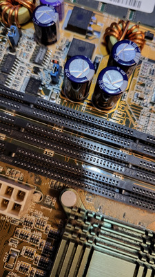
3v - Vio is produced by HIP6013 in upper right corner of the board https://datasheetspdf.com/pdf-file/1437189/Renesas/HIP6013/1 There is a 4 pin VIO jumper bank for tuning this supply line. Two capacitors closest to the coil CE31 CE32 are critical, so are CE28 CE29 CE30.
get a multimeter and measure voltage on L54 (on side closer to capacitor) in both DC and AC modes.
Try Vio jumper in all 3 positions. Try 3VSTB jumper (its near VIO jumper) in both possible positions.
Its possible 3V supply is really bad, but ram still manages to work with it while AMD751 and 82c686A (3V power their IO buffers) arent that tolerant.
Best case scenario would be Vio jumper missing, but sadly I can see one on your picture, its still possible somehow there is bad contact on that jumper, or whole 3V supply is producing bad /low/noisy voltage. Best check would be with oscilloscope (even crappy one).
Okay it took me a while to find where I put my multimeter. And the battery is dead again. Not a big deal it just takes a 9 volt, which I don't have on hand. I will pick one up after I get my daughter from school and I will try to get it tested after I spend some time with my daughter. She may want to help me test this. She loves to help.
rasz_pl wrote on 2022-10-22, 21:17:post code 07 "ROM BIOS checksum passed. CMOS shutdown register test to be done next." while VGA initialization is 2x something, […]
post code 07 "ROM BIOS checksum passed. CMOS shutdown register test to be done next."
while VGA initialization is 2x something, much laterTherefore bios chip is fine and has valid bios image flashed. There could be faint possibility someone flashed wrong bios, or replaced bios chips from wrong motherboard. But multiple reports of K7M having this very problem make it unlikely.
ISA and BIOS are sitting on low speed bus managed by 82c686A. PCI and AGP are sitting on separate busses managed by AMD751.
The only thing in common between PCI AGP and ISA graphic cards is CPU (you checked), AMD751, PSU (evidently working?), and 3V supply line.3v - Vio is produced by HIP6013 in upper right corner of the board https://datasheetspdf.com/pdf-file/1437189/Renesas/HIP6013/1 There is a 4 pin VIO jumper bank for tuning this supply line. Two capacitors closest to the coil CE31 CE32 are critical, so are CE28 CE29 CE30.
get a multimeter and measure voltage on L54 (on side closer to capacitor) in both DC and AC modes.
Try Vio jumper in all 3 positions. Try 3VSTB jumper (its near VIO jumper) in both possible positions.Its possible 3V supply is really bad, but ram still manages to work with it while AMD751 and 82c686A (3V power their IO buffers) arent that tolerant.
Best case scenario would be Vio jumper missing, but sadly I can see one on your picture, its still possible somehow there is bad contact on that jumper, or whole 3V supply is producing bad /low/noisy voltage. Best check would be with oscilloscope (even crappy one).
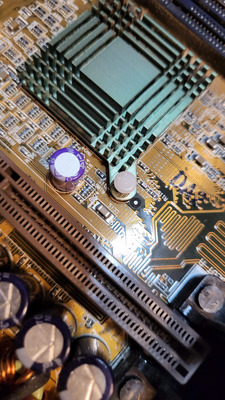
Hmm. I'm blind. I cannot find a chip labeled HIP6013. I found a chip called HIP6012CB. Is that the same?
L54 reads the following with 3VSBSLT on 2-3 pins and VIO with set to:
3.3V - 4.09 in DC and 8.1 in AC
3.4V - 4.24 in DC and 8.2 in AC
3.56V - 4.4 in DC and 8.6 in AC
L54 reads the following with 3VSBSLT on 1-2 pins and VIO set to:
3.3V - 3.94 in DC and 7.7 in AC
3.4V - 4.07 in DC and 8.0 in AC
3.56V - 4.42 in DC and 8.7 in AC
Honestly I have no clue if I am even doing it right. I checked the solder point on L54 that was closest to the RAM sockets and the Capacitors. On my multimeter the DC side has settings for 200m, 2, 20, 200, and 600, but the AC side only has settings for 200, and 600. So I don't even know if the information I was able to get is even remotely accurate. I am sorry if what I got didn't help.
-edit- I added a picture of the chip I did find
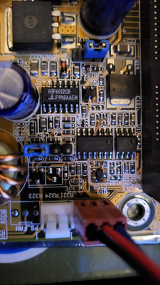
nathanieltolbert wrote on 2022-10-27, 23:33:Hmm. I'm blind. I cannot find a chip labeled HIP6013. I found a chip called HIP6012CB. Is that the same?
yes, interchangeable
nathanieltolbert wrote on 2022-10-27, 23:33:L54 reads the following with 3VSBSLT on 2-3 pins and VIO with set to: 3.3V - 4.09 in DC and 8.1 in AC 3.4V - 4.24 in DC and […]
L54 reads the following with 3VSBSLT on 2-3 pins and VIO with set to:
3.3V - 4.09 in DC and 8.1 in AC
3.4V - 4.24 in DC and 8.2 in AC
3.56V - 4.4 in DC and 8.6 in ACL54 reads the following with 3VSBSLT on 1-2 pins and VIO set to:
3.3V - 3.94 in DC and 7.7 in AC
3.4V - 4.07 in DC and 8.0 in AC
3.56V - 4.42 in DC and 8.7 in AC
the only difference between 3VSBSLT set at 1-2 or 2-3 is routing 3V to PCI slots and 3 more small capacitors. This big a difference, plus those insane AC readings make me believe 3V supply is very sick (good news!). Most likely culprit would be dried capacitors. Weird for Asus, on the other hand its 20 years old.
nathanieltolbert wrote on 2022-10-27, 23:33:Honestly I have no clue if I am even doing it right.
thats what I am here for 😀
nathanieltolbert wrote on 2022-10-27, 23:33:I checked the solder point on L54 that was closest to the RAM sockets and the Capacitors.
perfect. Just to make sure, the other multimeter lead was connected to ground, like for example poking into one of those funny screws in the LPT connector?
If yes then Its great you did AC measurements, 8V is absolutely crazy ripple and the fix will be easy.
rasz_pl wrote on 2022-10-28, 03:55:yes, interchangeable […]
nathanieltolbert wrote on 2022-10-27, 23:33:Hmm. I'm blind. I cannot find a chip labeled HIP6013. I found a chip called HIP6012CB. Is that the same?
yes, interchangeable
nathanieltolbert wrote on 2022-10-27, 23:33:L54 reads the following with 3VSBSLT on 2-3 pins and VIO with set to: 3.3V - 4.09 in DC and 8.1 in AC 3.4V - 4.24 in DC and […]
L54 reads the following with 3VSBSLT on 2-3 pins and VIO with set to:
3.3V - 4.09 in DC and 8.1 in AC
3.4V - 4.24 in DC and 8.2 in AC
3.56V - 4.4 in DC and 8.6 in ACL54 reads the following with 3VSBSLT on 1-2 pins and VIO set to:
3.3V - 3.94 in DC and 7.7 in AC
3.4V - 4.07 in DC and 8.0 in AC
3.56V - 4.42 in DC and 8.7 in ACthe only difference between 3VSBSLT set at 1-2 or 2-3 is routing 3V to PCI slots and 3 more small capacitors. This big a difference, plus those insane AC readings make me believe 3V supply is very sick (good news!). Most likely culprit would be dried capacitors. Weird for Asus, on the other hand its 20 years old.
nathanieltolbert wrote on 2022-10-27, 23:33:Honestly I have no clue if I am even doing it right.
thats what I am here for 😀
nathanieltolbert wrote on 2022-10-27, 23:33:I checked the solder point on L54 that was closest to the RAM sockets and the Capacitors.
perfect. Just to make sure, the other multimeter lead was connected to ground, like for example poking into one of those funny screws in the LPT connector?
If yes then Its great you did AC measurements, 8V is absolutely crazy ripple and the fix will be easy.
The point I used for ground was the metal ring around the screw mounting holes. Is that okay? I didn't think to use the hex nuts on the external ports as a grounding point. If those aren't ground, that may be why everything was way off. Is it possible that the 200V setting only for AC caused the weird AC voltage reads?
screw mounting holes should be fine
Have you ever desoldered capacitors from multilayer boards? 😀 Do you have any spare lowESR capacitors on hand? Just for testing you can piggyback (solder to their pins on the bottom side of pcb) a couple new capacitors directly onto CE28 CE29 CE30 near the ram slots without desoldering the old ones. Just have to make sure you get polarity right (stripes are on same leg as on old ones). Just for quick and dirty test any ~470-2000uF >=6.3V electrolytic capacitors will be fine.
If you want to see more of whats going on in the circuit you can download https://openboardview.org and https://www.xwfix.com/asus-motherboard-k7m-1-06-boardview/ you can see the diagram in 6013 sample circuit https://datasheetspdf.com/pdf/1437189/Renesas/HIP6013/1
I have some nichicons with the same rating 6.3V 1500uf. They're a little bit taller, but the rest of the dimensions are the same. The solder mask matches the polarity of the caps. I have replaced them and I will test the voltage now.