Reply 100 of 116, by feipoa

- Rank
- l33t++
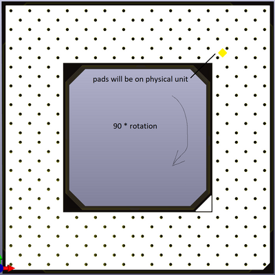
The shim:
a) make one shim as you've made it, but you'd want to reduce the size of the diamond pads to match the new rotator board
b) make one shim with regulator metalic through holes in place of the pads. No pads.
Sphere478 wrote on 2023-01-03, 22:52:It might be possible to do a offset thru hole. I don’t find it as elegant in this case though. And it would definitely be a full redesign.
I think it is best to create a part so more people can assemble it and with a greater degree of success. Elegance would only come afterwards in opinion. I still have my doubts as to my ability to assemble this.
Sphere478 wrote on 2023-01-03, 22:52:It would be even more cramped on the inner layers with the larger vias(now being larger plated thru holes for pins) also physically larger obviously.
The least space consuming would be to have the solder pads as the vias on the existing design.
Sphere478 wrote on 2023-01-03, 22:52:The only thing we can do better I think would be more layers. Ground planes are easy. […]
The only thing we can do better I think would be more layers. Ground planes are easy.
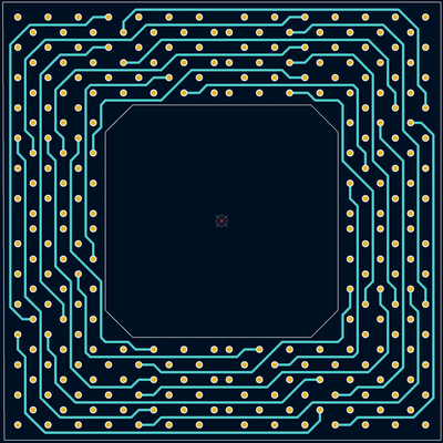
I could go 8 layer and spread out the doubled up traces. That might help. But going 8 layer to add ground doesn’t make a whole lot of sense. We would want more like 12 layers.
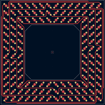
I think this 6 layer smd design is the best of cheap, organized, and compact.
It’s not great for signal interference though.
It looks like 6-layer and 8-layer will be the same cost, so doesn't matter.
Sphere478 wrote on 2023-01-03, 22:52:I don’t think there is going to be a 180* version.
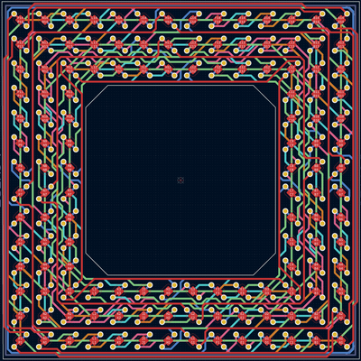
Here is why: It will have to have a high layer count or a bunch of uneven random spaghetti traces everywhere like shown earlier in thread.
Maybe it will be doable with pads in place of the vias. Perhaps look into auto-routing?
Sphere478 wrote on 2023-01-03, 22:52:It makes sense to simply try and bga stack this. It will give more distance between traces and cost will be low. Since the orders are already 5 per order you already get 2 180* versions per order.
I don't follow. The BGA stack you've presented looks to be a way to make blind vias. I'm not sure how this alters trace distance. You must be referring to another BGA stacking system. I think you mean to stack two of the existing 90 degree rotator boards together w/BGA to make a 180 degree. This is similar to stacking two assembled 90 degree units, but with less PGA conductor length involved. I have strong doubts I will be able to get this BGA assembly to solder properly. I would think that doing a direct re-route on the rotator board for 180 degree would yield the shortest trace lengths, at the expense of more time involvement.
Plan your life wisely, you'll be dead before you know it.