VOGONS


First post, by tsalat

User metadata
Rank Member
Rank
Member

Hi,

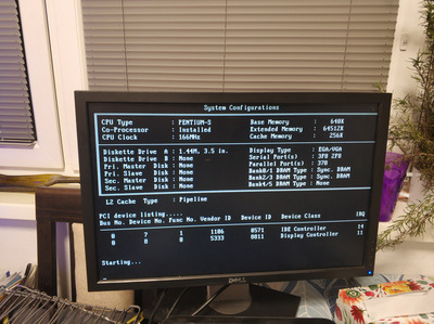
I have bought for a few bucks a old Amptron PM-8600 Socket 7 board in good looking condition. The board came without BIOS, the guy selling this and a few more board is taking all the ICs that are not hammered to the board out. Anyway, took another BIOS, flashed the BIOS from here there https://theretroweb.com/motherboards/s/amptro … 8600a#downloads and tried a good know Pentium 133 in it. Set all jumpers according to the manual, double checked with the print on the board and 1,2,3 turned it on. No beep, no post, just a click signal coming from the speaker - the debug card shows all power lines ok and a reset signal at the start.

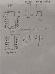
So, after some turn on/off, I have decided to check the voltage and removed the CPU (the CPU works in other board just fine) in the Socket 7, etc... and I have measured 5,1V - I have highlighted the position where I have measured the voltage in the image (link). Checked the IC next to the jumpers that sets the core voltage and it outputs 3,7V (I have set it to 3,5V), changed the jumpers to 2,5 and it outputs 2,6V - seems to work. Then I have moved to the Mosfet and the diode below the socket. And here I am really confused, the Mosfet gets around 10V input at one pin and the next two are having 5,1V - I am not sure honestly, but the 5,1V should be at both pins? The resistivity between the two pins outputting the 5,1V is like 50 ohms.

https://www.sylex.repository.3d-sphere.com/in … 4XdsyDttMdfTyGq

Right now I am not sure if the Mosfet is good, or something before. Anyone could confirm if the Mosfet is ok? Did I measure the core voltage at the right place?
I wrote down all the measurement in the picture (link).

Really thankful that I have found this community is really great and I am happy that I have found it!

thx, Tomas

Reply 1 of 18, by Martin85

User metadata
Rank Newbie
Rank
Newbie

I have the same board, mine posts and everything, but has fake or defective chips. Which is kinda "normal" on these boards. So when you access the bios, try to turn on and off external L2 cache. 😉 If you need some measurements I can provide them too...

Reply 2 of 18, by tsalat

User metadata
Rank Member
Rank
Member
Martin85 wrote on 2022-11-11, 19:45:

I have the same board, mine posts and everything, but has fake or defective chips. Which is kinda "normal" on these boards. So when you access the bios, try to turn on and off external L2 cache. 😉 If you need some measurements I can provide them too...

Hi, thank you for the reply. Could please measure the voltage on all three pins of the Mosfet FPN4503L? I have a feeling that since it is pumping 5,1V something there is faulty .

I will let you know if the cache will be working on this one, if it will come back to life 😀

Thx, tomas

Reply 3 of 18, by Martin85

User metadata
Rank Newbie
Rank
Newbie

I just took it from the "will think about it later" bin 😀 With a P166MHz (SL27K) it gives me (from left to right) 7V - 5.5V - 3V more or less (within 0.5V i guess since my multimeter is not the most exact one).

Anyway I have another power transistor there, not the same as yours:
https://datasheetspdf.com/pdf-file/118216/Sie … rGroup/BUZ102/1

EDIT: I have my CPUvoltage set to 2.8V!

Reply 4 of 18, by tsalat

User metadata
Rank Member
Rank
Member
Martin85 wrote on 2022-11-11, 20:17:
I just took it from the "will think about it later" bin :) With a P166MHz (SL27K) it gives me (from left to right) 7V - 5.5V - 3 […]
Show full quote

I just took it from the "will think about it later" bin 😀 With a P166MHz (SL27K) it gives me (from left to right) 7V - 5.5V - 3V more or less (within 0.5V i guess since my multimeter is not the most exact one).

Anyway I have another power transistor there, not the same as yours:
https://datasheetspdf.com/pdf-file/118216/Sie … rGroup/BUZ102/1

EDIT: I have my CPUvoltage set to 2.8V!

thank you a lot for this! Can you please do a picture of the board? the region around the CPU with the power transistor etc... is interesting for me.
I will compare to what I have a maybe use it to track down the error/issue 😀. I have the board at work and thus can do any measurement on Monday earliest but more ideas until then, better 😀.

thank you, tomas

Reply 5 of 18, by tsalat

User metadata
Rank Member
Rank
Member
Martin85 wrote on 2022-11-11, 20:17:
I just took it from the "will think about it later" bin :) With a P166MHz (SL27K) it gives me (from left to right) 7V - 5.5V - 3 […]
Show full quote

I just took it from the "will think about it later" bin 😀 With a P166MHz (SL27K) it gives me (from left to right) 7V - 5.5V - 3V more or less (within 0.5V i guess since my multimeter is not the most exact one).

Anyway I have another power transistor there, not the same as yours:
https://datasheetspdf.com/pdf-file/118216/Sie … rGroup/BUZ102/1

EDIT: I have my CPUvoltage set to 2.8V!

Hi, one more request. I am not sure now if the IC next to the jumpers that sets the core voltage is working properly since I have all the time an output voltage of 10V that comes to the Mosfet.
Could you please measure the pins I have highlighted on the IC TL494 (I think) in the image below? - with your current settings of 2.8V. Could you then take out the CPU and change the jumpers to 3.5V and measure the output again, only to see how it changes - CPU out since I dont want you fry it 😀. This will give me at least some idea.

https://www.sylex.repository.3d-sphere.com/in … 58JQQbbEqtn6Cte

thank you, Tomas

Reply 6 of 18, by Martin85

User metadata
Rank Newbie
Rank
Newbie

When I set the voltage to 3.5V the pin number 1 on the TL494 says 3.48, if set to 3.2 it gives me 3.18V... So it is working correctly, the pins number 9 and 10 doesn't give me anything. But the pin number 1 is an input, so there you should have the voltage you set with the jumpers and nothing else... It would be usefull knowing where does the regulation happen...

Reply 7 of 18, by tsalat

User metadata
Rank Member
Rank
Member
Martin85 wrote on 2022-11-14, 17:01:

When I set the voltage to 3.5V the pin number 1 on the TL494 says 3.48, if set to 3.2 it gives me 3.18V... So it is working correctly, the pins number 9 and 10 doesn't give me anything. But the pin number 1 is an input, so there you should have the voltage you set with the jumpers and nothing else... It would be usefull knowing where does the regulation happen...

thank you 😀

Can you please tell me if pin1 is the same as on the IC layout? And can you make a picture of how the connection looks like? It may be that there is something different between the mobo layouts.
I am asking because I am getting the set voltage through the jumpers on Pin2.

pin-layout-for-TL494-IC.png

Reply 9 of 18, by tsalat

User metadata
Rank Member
Rank
Member
Martin85 wrote on 2022-11-14, 19:22:

sorry, i meant i have the 3.5V on the pin number 2... like you have!

Heh, no problém, I am grateful for your help. And pins9 and 10 are at 0V, that's strange? The Mosfet I have there, that is connected to VCC2 on the socket, is fed by those pins but it seems to be always 10V. I am not sure how the circuit looks after and if some divider is after the Mosfet but I would expect that the IC is changing the E2 and E1 according to the pin2 and that is then converted near the Mosfet. Is your, I think you mentioned you have a power transistor instead the Mosfet there, changing the voltage at input, you mentioned 7V, while you change the jumpers on the core voltage? Can you measure all pins on the IC TL 494.

I know, I am asking for a lot, sorry 🙁 but I want to make sure that before I will desolder it away to see more that I am not doing it for waste, heh.

Thx, Tomas

Reply 10 of 18, by tsalat

User metadata
Rank Member
Rank
Member

Hi,

a small update. I have decided to replace the TL494CN and add a socket to the position. The de-soldering, even with a vacuum pump station, was a nightmare but ok, heh. After replacing the TL494CN I am getting at most pins the same readings, however, at pin 9 and 10 on which I have 10V before, I have 0V.

Martin85 wrote on 2022-11-14, 17:01:

So it is working correctly, the pins number 9 and 10 doesn't give me anything

I have remembered that Martin pointed no voltage at those pins as well... hmmm.. seems like a progress but the voltage on the core is still 5V and the voltage on the mosfet now is 0(this was 10V before),5,5V.
What would be helpful now will be the readings from all pins on the TL494 just to make sure I am getting the I-O at the same level as by a working board.

My next step would be to look on the mosfet a bit more.

thx, tomas

Reply 11 of 18, by Martin85

User metadata
Rank Newbie
Rank
Newbie

Here are my readings, sorry couldn't do it faster...
Also borrowed a much more exact multimeter from work... 😉

Attachments

Reply 12 of 18, by Martin85

User metadata
Rank Newbie
Rank
Newbie

These are reading without the processor mounted...
With the processor mounted and set to 2.8V by thw jumpers, i get at the BUZ102 (sipmos power transistor N channel) 5.9 - 4.96 - 2.8

Reply 13 of 18, by tsalat

User metadata
Rank Member
Rank
Member
Martin85 wrote on 2022-11-22, 10:33:

These are reading without the processor mounted...
With the processor mounted and set to 2.8V by thw jumpers, i get at the BUZ102 (sipmos power transistor N channel) 5.9 - 4.96 - 2.8

Martin85 wrote on 2022-11-22, 10:22:

Here are my readings, sorry couldn't do it faster...
Also borrowed a much more exact multimeter from work... 😉

Hi Martin, thank you so much for your time! It is so helpful to have your readings right now and compare them to what I have.
It seems that replacing the TL494 made a difference, the E1,E2 that were before at 10V are now 0V and I have the same readings as you have. I do not have a CPU now but I will try it later on with an CPU to see what will be difference - tomorrow I think. Really keen to see if this was the error or there is something else 😀

thank you, Tomas

Reply 14 of 18, by tsalat

User metadata
Rank Member
Rank
Member

H

Martin85 wrote on 2022-11-22, 10:33:

These are reading without the processor mounted...
With the processor mounted and set to 2.8V by thw jumpers, i get at the BUZ102 (sipmos power transistor N channel) 5.9 - 4.96 - 2.8

It's alive!!!! Ohh, happy now, heh. I am so glad you could do the readings since without them I would be a bit lost and would not change the TL494 in the first place!

Perfect, heh.

However, one thing, I have add 2x 128MB SDRAM to the board and the board recognize them as 32MB and thus 64MB in total. I know these are working properly since I have tested them before. Any idea why? Compatibility issues?

Thx, tomas

Attachments

  • IMG_20221122_183949.jpg
    Filename
    IMG_20221122_183949.jpg
    File size
    1.47 MiB
    Views
    830 views
    File comment
    Boot up
    File license
    Fair use/fair dealing exception

Reply 15 of 18, by Martin85

User metadata
Rank Newbie
Rank
Newbie

Yes, I have the same problems with SDRAM... everytime it gives a random number 😁 This board is plagued... Do you have L2 cache enabled? Lucky you, mine stopped working...

Reply 16 of 18, by tsalat

User metadata
Rank Member
Rank
Member
Martin85 wrote on 2022-11-23, 13:57:

Yes, I have the same problems with SDRAM... everytime it gives a random number 😁 This board is plagued... Do you have L2 cache enabled? Lucky you, mine stopped working...

hi, yes L2 Cache is enabled and it seems to be working. At this moment I am afraid to sneeze on it 😀 but glad it is alive again.

again, thank you a lot for your help.

tomas

Attachments

  • PM-8600.jpg
    Filename
    PM-8600.jpg
    File size
    48.39 KiB
    Views
    798 views
    File comment
    speedsys
    File license
    Fair use/fair dealing exception

Reply 17 of 18, by Martin85

User metadata
Rank Newbie
Rank
Newbie

Hey, after a long time, could you take a close photo of the CACHE chips? Considering changing them, but I see from your photos that you have different chips... Hopefully I can find some of those chips somewhere.

Reply 18 of 18, by tsalat

User metadata
Rank Member
Rank
Member
Martin85 wrote on 2023-08-23, 16:42:

Hey, after a long time, could you take a close photo of the CACHE chips? Considering changing them, but I see from your photos that you have different chips... Hopefully I can find some of those chips somewhere.

Hi, here you go with the pictures, let me know if you need something else:

https://www.sylex.repository.3d-sphere.com/in … G9H8ste3Qb3N9jk
https://www.sylex.repository.3d-sphere.com/in … MQZmcoF6JtTTN9Q

best regards, Tomas