First post, by ziggy587

- Rank
- Newbie
Hey, everyone!
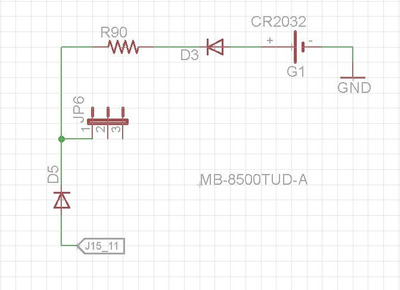
So I'm having an issue with the soft power switch on a Socket 7 motherboard. This is actually the same board from another thread I posted, I had an issue with voltage at the PS/2 ports. It's a Biostar MB-8500TUD-A.

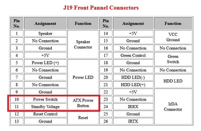
So this is one of those baby AT boards that was on the verge of ATX. This board has the P8/P9 AT power connector as well as a 20-pin ATX power connector, although my exact revision did not populate the ATX connector. I tested continuity between the unpopulated ATX connector socket and the P8/P9 connectors, and everything checked out. So I decided to install the 20-pin connector so I can use an ATX power supply without any adapters, as well as use an ATX case. (and built in power button). I've been testing the board out for a few days now using a P8/P9 to ATX adapter, and aside from the aforementioned PS/2 voltage issue, everything seems OK. I don't think adding the missing 20-pin connector is an issue, I don't see any other missing components on the board that seem like they would have something to do with the power-on signal, but I thought I should mention it just in case.
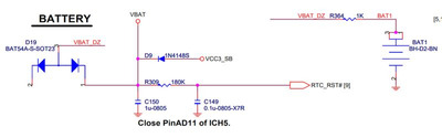
Now here's the issue: When I plug an ATX power supply into the newly installed 20-pin connector, as soon as I flip the switch on the back of the PSU the board powers itself on.
I don't think I fully understand how the soft power works on ATX boards. I know that when the power-on signal (the green wire) is pulled low, the PSU will turn on. But I thought it was connected directly to the momentary switch, and only needed to briefly be pulled low to turn the PSU on or off. That seems to be how the reset switch works, so I assumed the power switch worked the same way. But it appears that there must be a circuit between the power-on signal from the PSU and the soft power switch. Now I'm guessing that the power-on signal needs to be HELD low, and this is accomplished on the motherboard instead of in the PSU. So that would mean the momentary switch activates a circuit that latches the signal low. And then hitting the power switch again will unlatch the signal. Is this correct?
I tried searching for the ATX soft power circuit.... Is there a standard circuit that all boards use? I'm assuming there is an issue with this circuit on my motherboard. I tried to trace it out to find the components, but that proved to be extremely difficult.
I have thought of a work around. I know I could just ground the power-on wire via a SPST switch, but I'd rather use the case's built in power button. So I thought of this: I could splice out the power-on wire from my 20-pin connector, then build my own soft power circuit, and hook the case's power switch up to that. But I would like to investigate the problem if I can. For one, so I can be sure it isn't going to cause any further problems. But also for the learning experience of it.