VOGONS


First post, by Wilius

User metadata
Rank Member
Rank
Member

Greetings everyone.

This is an update on my previous post.
I have a major problem with my Compaq SLT/286.
Yesterday, I discovered that the floppy disk drive (Cititzen OSDA-52B) is broken.
The top magnetic head came loose because the adhesive weakened.
This drive has a special 26 pin connector that I don’t know much about.
Can I use another drive with a standard 34 pin connector? Or where can I find the same, or a similar drive model?
I found one on eBay, but I prefer not to buy from international sellers. (I’m from Germany)
Please let me know if you have any suggestions or experience with this issue.
Thank you very much.

Reply 1 of 12, by ediflorianUS

User metadata
Rank Member
Rank
Member

yes you need to re-do manual pin-out
https://www.youtube.com/watch?v=1hTCTtKnE1k ,
you can also fix your current floppy you just need to search on youtube how to do-it

Youtube is your friend. pt2 pt3

first-thing's first , contact-clean full drive ,isoprop-alcohol clean head, remount everything as it was and if not working-reflow pcb-pin contacts. then check for drainage (resistance on 5v pins). you can also try to change the head only from standard floppy. may work if it's close enough.

My 80486-S i66 Project

Reply 2 of 12, by Thermalwrong

User metadata
Rank Oldbie
Rank
Oldbie

Beware, the Compaq's Citizen floppy drives in that era are a unique pinout. They're 26 pins but totally different layout, I have personal experience with the drive getting fried if plugged into a regular 26-pin floppy connection.
The Citizen OSDA-52B drive isn't one that I have, but I was able to get my Citizen VIDA-15b in my Compaq LTE Lite to work using the pinout on this vcfed forum post: https://forum.vcfed.org/index.php?threads/com … r-pinout.62311/
The latter unknown pins should be the same as on my VIDA-15B which you can see here: Re: What retro activity did you get up to today? - but test for yourself! On your current drive, the pin 23 should connect to pin 26 (motor on) and the pin 24 should connect to pin 25 (drv sel)

I don't know much about what the SLT looks like inside since I've only got an LTE laptop. Looks like the 26-pin 2.54mm connector is on a ribbon cable so you couldn't really fit a regular 3.5" desktop size floppy in there with an adapter cable, I think. Could you take some pictures to show what the clearance is like?
How long is the OSDA-52B?

I made up an adapter PCB that hasn't yet been sent off for production, which converts a regular 26-pin floppy into the Citizen VIDA-15B pinout - it would not be hard for me to make one that does the same for the OSDA-52B's 2.54mm pins instead. Then you could fit a regular desktop drive if it's short enough.

ediflorianUS: cool, I wasn't aware of that channel and his content looks interesting, thanks 😀

Reply 3 of 12, by Wilius

User metadata
Rank Member
Rank
Member

First of all, I want to thank you for your quick replies.
I really appreciate it.
I’m sorry for the late response, it’s been a busy week.

ediflorianUS wrote on 2023-03-12, 16:16:

first-thing's first , contact-clean full drive ,isoprop-alcohol clean head, remount everything as it was and if not working-reflow pcb-pin contacts. then check for drainage (resistance on 5v pins). you can also try to change the head only from standard floppy. may work if it's close enough.

As you suggested, I cleaned the entire drive, including the magnetic heads and every single connector.
However, during the disassembly, I noticed a burnt smell coming from the floppy drive.
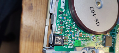
And sure enough, there is a blown resistor on the controller PCB. (I’m attaching some photos for reference.)
Furthermore, I noticed weird stains and rust everywhere. I think my Compaq SLT/286 has liquid damage, or at least the floppy drive.

Unfortunately, I made a mistake during the reassembly and damaged the connector for the stepper motor.
The little blue plastic tab came loose because the glue disintegrated.
I can’t glue it back in place because my hands are too shaky (I have ADHD and holding still is not my strength).

I think it’s time to give up on this floppy drive.
Even if I had been more careful, I believe the drive would’ve been unfixable anyways.
It is likely that both heads are dead because they crashed with each other.

Thermalwrong wrote on 2023-03-13, 02:49:

I don't know much about what the SLT looks like inside since I've only got an LTE laptop. Looks like the 26-pin 2.54mm connector is on a ribbon cable so you couldn't really fit a regular 3.5" desktop size floppy in there with an adapter cable, I think. Could you take some pictures to show what the clearance is like?
How long is the OSDA-52B?

I made up an adapter PCB that hasn't yet been sent off for production, which converts a regular 26-pin floppy into the Citizen VIDA-15B pinout - it would not be hard for me to make one that does the same for the OSDA-52B's 2.54mm pins instead. Then you could fit a regular desktop drive if it's short enough.

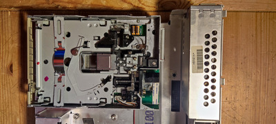
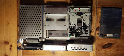
It looks like there’s enough clearance to fit in a regular desktop drive.
In fact, I’m pretty sure the Citizen OSDA-52B is a “normal” 3.5” drive (at least in terms of its size).
With that in mind, I think your adapter PCB should work just fine.
I’m attaching some photos.
Feel free to ask if you need more information.

I hope this helps! Let me know if you need anything else.

Attachments

  • IMG_20230315_180024.jpg
    Filename
    IMG_20230315_180024.jpg
    File size
    275.43 KiB
    Views
    623 views
    File comment
    This picture shows the blown resistor
    File license
    Fair use/fair dealing exception
  • IMG_20230315_175308.jpg
    Filename
    IMG_20230315_175308.jpg
    File size
    870.87 KiB
    Views
    623 views
    File comment
    the contacts of the indication LED are rusted
    File license
    Fair use/fair dealing exception
  • IMG_20230315_175223.jpg
    Filename
    IMG_20230315_175223.jpg
    File size
    222.37 KiB
    Views
    623 views
    File comment
    here you can see some of the weird stains
    File license
    Fair use/fair dealing exception
  • IMG_20230315_174819.jpg
    Filename
    IMG_20230315_174819.jpg
    File size
    1.27 MiB
    Views
    623 views
    File license
    Fair use/fair dealing exception
  • IMG_20230315_174811.jpg
    Filename
    IMG_20230315_174811.jpg
    File size
    1.37 MiB
    Views
    623 views
    File license
    Fair use/fair dealing exception

Reply 4 of 12, by Thermalwrong

User metadata
Rank Oldbie
Rank
Oldbie

Thanks for the pictures, I agree that it's probably possible to fit a regular 34-pin floppy or gotek in there. I'm just starting on updating the schematic for OSDA26pin > Regular 34 pin floppy + power connector. Hopefully a little molex power cable can fit in there to power the drive. Those will probably be just little 2.54mm headers since that's easiest.

Can you check whether pin 23 connects to pin 26, then whether pin 24 connects to pin 25? If they're not then I'll have to add some solder jumpers for drive select.

Reply 5 of 12, by Wilius

User metadata
Rank Member
Rank
Member
Thermalwrong wrote on 2023-03-18, 21:12:

Can you check whether pin 23 connects to pin 26, then whether pin 24 connects to pin 25? If they're not then I'll have to add some solder jumpers for drive select.

I've measured the continuity with my Multimeter and it looks like, none of these pins are connected to each other.
I did the measurements on the floppy drive.

To avoid any misunderstanding, did you want me to check the connector from the motherboard, or the floppy drive?

Reply 6 of 12, by Deunan

User metadata
Rank Oldbie
Rank
Oldbie
Wilius wrote on 2023-03-18, 17:48:

I think it’s time to give up on this floppy drive.
Even if I had been more careful, I believe the drive would’ve been unfixable anyways.
It is likely that both heads are dead because they crashed with each other.

FYI: That's not a resistor, it's a coil/choke. Looks to be a filter for the power supply, for a temporary fix even a piece of wire will do. But the question is why it burned, it would mean there's a short somewhere - possibly due to the now damaged stepper motor connector. Well, connectors can be replaced, or the cable can be soldered directly (many drives are like that).

Heads can come into contact with each other (in fact they do if the drive is closed with no floppy), that won't damage them. But if any of the heads are loose then it's not enough to glue them back, the alignment will be way off, and frankly also azimuth which is not fixable once the glue sets it, so any attempts to glue the head back would require good eyes (and preferably marks from orginal glue spots to try and mach that). Steady hands are a big help but can be worked around with some patience, sticky tape and/or small alligator clips.

Reply 7 of 12, by Wilius

User metadata
Rank Member
Rank
Member
Deunan wrote on 2023-03-19, 12:01:

FYI: That's not a resistor, it's a coil/choke. Looks to be a filter for the power supply, for a temporary fix even a piece of wire will do. But the question is why it burned, it would mean there's a short somewhere - possibly due to the now damaged stepper motor connector. Well, connectors can be replaced, or the cable can be soldered directly (many drives are like that).

I can confirm that the damaged motor connector is not the cause of the problem.
The component was already burnt before I damaged the connector.

I apologize for the stupid question, but are you sure that L102 isn't a resistor?
It looks like a 4 band resistor to me.
But judging by your expertise, you're probably right and I'm wrong.
I've just never seen a coil before, that looks like a resistor. How intriguing.
As you may figured, i'm not an expert in this field, so i'm open to your opinion.

Deunan wrote on 2023-03-19, 12:01:

Heads can come into contact with each other (in fact they do if the drive is closed with no floppy), that won't damage them. But if any of the heads are loose then it's not enough to glue them back, the alignment will be way off, and frankly also azimuth which is not fixable once the glue sets it, so any attempts to glue the head back would require good eyes (and preferably marks from orginal glue spots to try and mach that). Steady hands are a big help but can be worked around with some patience, sticky tape and/or small alligator clips.

As mentioned earlier, with my shaky hands, this is pretty much not doable for me.
I appreciate your helpful advice, though.

Reply 8 of 12, by Deunan

User metadata
Rank Oldbie
Rank
Oldbie
Wilius wrote on 2023-03-19, 16:38:

I apologize for the stupid question, but are you sure that L102 isn't a resistor?
It looks like a 4 band resistor to me.

Pretty sure. First, the L marking suggests that. It's near the power capacitors and has pretty beefy copper traces which makes me belive it's a power filter. Second, there L101 below and that is pretty much a wire going throuch a ferrite core - that's also a choke/coil but very simple one, effective for higher frequencies only (radio and above). It has very low DC resistance though which is required for things with higher current draw like motors.

But don't take my word for it, check it with an ohm meter. Maybe it's damaged but not yet open, in that case you should see a few ohms at most (I'd expect an ohm or less).

Reply 9 of 12, by Jo22

User metadata
Rank l33t++
Rank
l33t++

I also think that it may be a choke.

In the past, I've bought some for my radio hobby in an electronics store.
Such a choke looks like a fat resistor.

Also, it's possible to build a choke using a bog standard resistor and some fine wire wound around it.

"Time, it seems, doesn't flow. For some it's fast, for some it's slow.
In what to one race is no time at all, another race can rise and fall..." - The Minstrel

//My video channel//

Reply 10 of 12, by Wilius

User metadata
Rank Member
Rank
Member

Sorry for the late response.

I just realized what an absolute idiot I am.

It literally says "L102" on the PCB.
Components with an "L" marking are indeed coils or chokes.
If it was an actual resistor, it should've been marked as "R102", which it isn't.
I apologize for being such a dunce, I should've known better.
Why I didn't notice it sooner is beyond me.
Thank you Deunan and Jo22 for making it clear to me.
I appreciate that.

Reply 11 of 12, by ediflorianUS

User metadata
Rank Member
Rank
Member

"Unfortunately, I made a mistake during the reassembly and damaged the connector for the stepper motor.
The little blue plastic tab came loose because the glue disintegrated.
I can’t glue it back in place because my hands are too shaky (I have ADHD and holding still is not my strength)." - Can't you use a glue-gun to fit the cable then solder iron if -need-be.?

My 80486-S i66 Project

Reply 12 of 12, by Wilius

User metadata
Rank Member
Rank
Member
ediflorianUS wrote on 2023-04-20, 10:50:

"Unfortunately, I made a mistake during the reassembly and damaged the connector for the stepper motor.
The little blue plastic tab came loose because the glue disintegrated.
I can’t glue it back in place because my hands are too shaky (I have ADHD and holding still is not my strength)." - Can't you use a glue-gun to fit the cable then solder iron if -need-be.?

Thank you for attempting to help me, but I'm not quite sure what you want me to do here.

Just for the record, the plastic tab is tiny.
Besides that, the gluing job needs to be super precise.
If the connector is thicker than 0.4 mm and wider than 6 mm, it won't fit anymore.
I doubt, I'll be able to use a glue-gun to fix this mess.

Sure, I could try to solder the cable in place, but it wouldn't really matter, since the drive has other major defects, which are unfixable.