VOGONS


First post, by nathanieltolbert

User metadata
Rank Member
Rank
Member

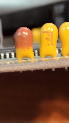
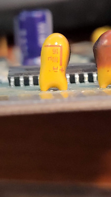
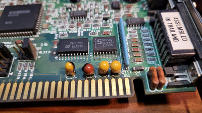
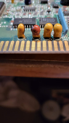
Hello everyone. A friend of mine out of state needed some work done on their 486 machine that was having problems. Turns out the cache chips had gone bad and it was a simple fix. When he sent the motherboard he also sent a MediaVision Pro Audio Spectrum 16 sound card to let me try it out because I have never had a chance to take a look at one in person. He had purchased it online at an auction site and he hadn't used it yet either. I installed the card in a VLB 486 board I have and I pressed the power button. There was a rapid ticking sound and then a woosh and I could see small flames shooting up from the board and the case rapidly filled with smoke as I hit the power button and pulled the power cable. I pulled the card and checked the motherboard. The motherboard is fine as is everything attached to it. But the card has two burned yellow parts near the larger row of ISA connectors. They are labeled CT7 and CT8. They are both damaged and I can't read the values on the parts. Are this capacitors? Can I replace these safely and get the card working again? I am trying to get the photos of the board uploaded so I can share them. As soon as they are available I will share them. Also, if they can be replaced and the card can be saved, should I replace all of these yellow parts?

Reply 1 of 39, by nathanieltolbert

User metadata
Rank Member
Rank
Member

Okay here are the pictures I took of the components that failed. The pictures I got with my phone look close enough to read the values, but I'm not 100% certain. It looks like they say 10u and 16? Is that 16 volts? There also appears to be an orientation of positive and negative pins? I feel like I'm grasping at straws. Please let me know what you think? Thank you.

Attachments

  • 20230316_024236.jpg
    Filename
    20230316_024236.jpg
    File size
    243.66 KiB
    Views
    1392 views
    File comment
    CT8 - extensively burned - is the value 10u and 16?
    File license
    Public domain
  • 20230316_024231.jpg
    Filename
    20230316_024231.jpg
    File size
    240.83 KiB
    Views
    1392 views
    File comment
    close up of number values on component
    File license
    Public domain
  • 20230316_024101.jpg
    Filename
    20230316_024101.jpg
    File size
    768.09 KiB
    Views
    1392 views
    File comment
    Another picture to show extent of failure
    File license
    Public domain
  • 94e5c6a2-b4ae-4efd-9f6d-39a729eba43f.jpg
    Filename
    94e5c6a2-b4ae-4efd-9f6d-39a729eba43f.jpg
    File size
    373 KiB
    Views
    1392 views
    File comment
    picture of row
    File license
    Public domain

Reply 2 of 39, by konc

User metadata
Rank l33t
Rank
l33t

Yes those are tantalum capacitors and when they fail they do it spectacularly, most of the times they explode. Nothing to worry too much about, just replace them and see. Most probably it's just them. They do have a polarity and the value I see on the not-burned one is 10μF / 16V.

Reply 3 of 39, by vstrakh

User metadata
Rank Member
Rank
Member

The exact value is not that important, just make sure the voltage rating is not lower. When I was ordering some, I only found caps rated 35v instead of 16v.
10uF, 20uF - shouldn't matter at all.

Reply 4 of 39, by Pierre32

User metadata
Rank Oldbie
Rank
Oldbie

Welcome to exploding tantalums 😁 Don't sweat it mate, follow the advice here and if you're not confident doing the soldering job, find someone who is and accepts payment in beer.

Reply 5 of 39, by Jo22

User metadata
Rank l33t++
Rank
l33t++
vstrakh wrote on 2023-03-16, 08:53:

The exact value is not that important, just make sure the voltage rating is not lower. When I was ordering some, I only found caps rated 35v instead of 16v.
10uF, 20uF - shouldn't matter at all.

Well, the µF values do matter, technically, since they do both power buffering and low-pass filtering (RF noise etc).

But of course I agree with you that you're right if you say that chosing other values don't cause any harm. 🙂
There's plenty of room for variation. Personally, I would use 47 µF as the maximum here, though.

Ideally, the filtering performance could be even improved by installing multiple caps with different values in parallel.
Each of them will then individually stop RF noise, ripple etc.
Say 100 nF, 1 µF, 10 µF. Maybe 10 nF, too.

Voltage.. I "hate" 16v types with pleasure, next to the 6,3v types.
Because they fail the most from my personal experience.
I assume that's because they're being operated close to thear maximum voltage of 12v all the time.
While not measurable due to latency of muktimeters,
I assume that those filtering caps will be tortured
by voltage spikes over and over in the milliseconds range.
Like a metal wire that's being bent back and forth, they'll eventually break.

So I really recommend choosing something bigger than 16v or 6.3v during replacement, even if it's merely rated for a few volts more.
But that's just me. Others surely will disagree and say it's not necessary. 🙂

"Time, it seems, doesn't flow. For some it's fast, for some it's slow.
In what to one race is no time at all, another race can rise and fall..." - The Minstrel

//My video channel//

Reply 6 of 39, by nathanieltolbert

User metadata
Rank Member
Rank
Member

Thank you for the information. With them being PTH, I'm confident I can remove and replace. I wasn't sure what they were. Most of the capacitors I work with are electrolytic, so I wasn't certain these were capacitors. So as a safety precaution, I'm going to replace all 4 of the tantalums there in that row, they are all labeled 10u 16. Looking around I found some 24V ones that are 10u. Do you think those will work? And.... Mouser is down... Hmm. I may have to wait a bit to order. Maybe Digikey has them as well. Any brands I should avoid?

Reply 7 of 39, by bogdanpaulb

User metadata
Rank Member
Rank
Member

For testing purposes , in this case , you can just remove the ones that failed and test the card . Then solder the new ones when you have them. Usually is best practice to replace all of them when you have new parts because the 'olds' that didn't fail , can at any moment .

Reply 8 of 39, by shevalier

User metadata
Rank Member
Rank
Member
Jo22 wrote on 2023-03-16, 09:13:

I "hate" 16v types with pleasure, next to the 6,3v types.

For old-type tantalum capacitor voltage derate is almost by 2.
Also, have derating by temperature.
For 12V power rail and unlimited current applicable 25V tantalum capacitor ( 20 - is risky).

It is easier to put standard modern electrolytic capacitors at 47uF * 16V, even for general use.

Aopen MX3S, PIII-S Tualatin 1133, Radeon 9800Pro@XT BIOS, Diamond monster sound MX300
JetWay K8T8AS, Athlon DH-E6 3000+, Radeon HD2600Pro AGP, Audigy 2 Value

Reply 9 of 39, by Horun

User metadata
Rank l33t++
Rank
l33t++

I agree replacing with new modern Electrolytics would be in some ways better. The only quirk is that Electro's do not filter as well at very high frequency (is why you sometimes see a 0.1 or 0.01mF ceramic in parallel in certain circuits).

Hate posting a reply and then have to edit it because it made no sense 😁 First computer was an IBM 3270 workstation with CGA monitor. Stuff: https://archive.org/details/@horun

Reply 10 of 39, by shevalier

User metadata
Rank Member
Rank
Member
Horun wrote on 2023-03-18, 00:43:

I agree replacing with new modern Electrolytics would be in some ways better. The only quirk is that Electro's do not filter as well at very high frequency (is why you sometimes see a 0.1 or 0.01mF ceramic in parallel in certain circuits).

Old-type tantalum to0 🙁
They are also quite low-frequency, and their ESR also increases over time.
During the repair, they all need to be soldered and checked with an ESR meter - they should be up to 0.1-0.3 Ohm, depending on the denomination.
0.1uF - old school shunting (70-80s), when 0.1uF was the maximum capacitance available.

According to the modern concept of RF shunting, this is the maximum capacitance of the X5R / X7R type of dielectric in the 1206 case + about 1 microfarad in 0805 X5R / X7R + 0.047 microfarad in 0603 C0G dielectric.
https://ksim3.kemet.com/
Therefore, a modern electrolyte will suffice for a direct replacement.

Aopen MX3S, PIII-S Tualatin 1133, Radeon 9800Pro@XT BIOS, Diamond monster sound MX300
JetWay K8T8AS, Athlon DH-E6 3000+, Radeon HD2600Pro AGP, Audigy 2 Value

Reply 11 of 39, by nathanieltolbert

User metadata
Rank Member
Rank
Member

Okay I saw 10u at 25v with the proper spacing. Is Kyocera okay as a tantalum? The only other one that shows up is one called Kemet? Which would be the preferable brand? And on top of replacing the four next to the ISA edge connector, should I replace *all* of the tantalums on the board? There are 16 on the board and I can see the values on 15 of them. They all appear to be the same. but there is one I cannot see the value of at all. Should I also replace the electrolytic caps as well you think? There's two 16V/1000uf with 3.8mm or so spacing and two 16V/100uf with roughly 2mm spacing (sorry it's really small and I am having difficulty getting an exact reading with my digital caliper). I mean, I'm going to have to order the tantalums, I can replace the nichicon electrolytics that are on the board at the same time. They don't show any bulging or issues, but I understand that it's difficult to tell sometimes.

Reply 13 of 39, by mkarcher

User metadata
Rank l33t
Rank
l33t
nathanieltolbert wrote on 2023-03-18, 06:06:

And on top of replacing the four next to the ISA edge connector, should I replace *all* of the tantalums on the board? There are 16 on the board and I can see the values on 15 of them.

Those 16V tantalums mostly explode when they are old and suddenly get 12V. If should be sufficient to replace those tantalum caps that are connected to the -12V or the +12V supply on the ISA bus. The caps on the 5V rails are much less likely to fail. (This is general advice for 90's hardware; it's well-known that on the old 5150-era IBM stuff tantalums fail everywhere).

Reply 14 of 39, by shevalier

User metadata
Rank Member
Rank
Member
vstrakh wrote on 2023-03-18, 06:52:

The generally accepted view on this is that electrolytics are not the proper replacement for tantalums.

Yeah.
A modern electrolytic capacitor is not a replacement for a modern tantalum capacitor.
Modern electrolytic capacitor versus 30 year old tantalum?

PS
https://industrial.panasonic.com/ww/products/ … hybrid-aluminum
And then Panasonic came up with something different ...

Aopen MX3S, PIII-S Tualatin 1133, Radeon 9800Pro@XT BIOS, Diamond monster sound MX300
JetWay K8T8AS, Athlon DH-E6 3000+, Radeon HD2600Pro AGP, Audigy 2 Value

Reply 15 of 39, by shevalier

User metadata
Rank Member
Rank
Member
mkarcher wrote on 2023-03-18, 08:39:

Those 16V tantalums mostly explode when they are old and suddenly get 12V.

https://www.avx.com/docs/techinfo/VoltageDera … mCapacitors.pdf

Aopen MX3S, PIII-S Tualatin 1133, Radeon 9800Pro@XT BIOS, Diamond monster sound MX300
JetWay K8T8AS, Athlon DH-E6 3000+, Radeon HD2600Pro AGP, Audigy 2 Value

Reply 16 of 39, by Jo22

User metadata
Rank l33t++
Rank
l33t++
shevalier wrote on 2023-03-18, 12:38:
mkarcher wrote on 2023-03-18, 08:39:

Those 16V tantalums mostly explode when they are old and suddenly get 12V.

https://www.avx.com/docs/techinfo/VoltageDera … mCapacitors.pdf

"Hence a minimum derating of 20% is sufficient in all applications; so, for example, a 4V capacitor can be safely used on a 3.3v power rail and a 6.3v rated capacitor on a 5.5v rail"

Jesus! What a nonsense. Practice and theory are entirely separate things. 🙄

Edit: That being said, it might be true under lab conditions, yes.

"Time, it seems, doesn't flow. For some it's fast, for some it's slow.
In what to one race is no time at all, another race can rise and fall..." - The Minstrel

//My video channel//

Reply 17 of 39, by nathanieltolbert

User metadata
Rank Member
Rank
Member

Okay. I'm trying to buy the Tantalums. I have multiple listings. Some of them are labeled ESR. Should I go with those? Some say 10%, others say 20%. Should I go with the 20% ones or the 10% ones? I want to make sure I get ones that will last. The voltage I plan to go with is 25V, if that won't cause issues.

Reply 18 of 39, by bogdanpaulb

User metadata
Rank Member
Rank
Member

10% tolerance (if the price gap is not that big) , standards , no low ESR in this case. Brands available ? Kemet is better , but Kyocera is ok also (a 20% 'good brand' can be better then a 10% 'no name').

Reply 19 of 39, by nathanieltolbert

User metadata
Rank Member
Rank
Member

The price for Kemet is 2.42 a piece, and Kyocera is 1.04 a piece. But all of the Kyocera that are showing up have ESR listed next to them. Those prices are both for 10% tolerance. I am looking on Mouser.