VOGONS


Reply 20 of 39, by bogdanpaulb

User metadata
Rank Member
Rank
Member

Go with the cheapest TAP106K025SCS , just check the lead spacing. There is no point in getting something more expensive if you will not 'mod' the filtering caps :

Jo22 wrote on 2023-03-16, 09:13:
Well, the µF values do matter, technically, since they do both power buffering and low-pass filtering (RF noise etc). […]
Show full quote

Well, the µF values do matter, technically, since they do both power buffering and low-pass filtering (RF noise etc).

But of course I agree with you that you're right if you say that chosing other values don't cause any harm. 🙂
There's plenty of room for variation. Personally, I would use 47 µF as the maximum here, though.

Ideally, the filtering performance could be even improved by installing multiple caps with different values in parallel.
Each of them will then individually stop RF noise, ripple etc.
Say 100 nF, 1 µF, 10 µF. Maybe 10 nF, too.

Voltage.. I "hate" 16v types with pleasure, next to the 6,3v types.
Because they fail the most from my personal experience.
I assume that's because they're being operated close to thear maximum voltage of 12v all the time.
While not measurable due to latency of muktimeters,
I assume that those filtering caps will be tortured
by voltage spikes over and over in the milliseconds range.
Like a metal wire that's being bent back and forth, they'll eventually break.

So I really recommend choosing something bigger than 16v or 6.3v during replacement, even if it's merely rated for a few volts more.
But that's just me. Others surely will disagree and say it's not necessary. 🙂
Reply 21 of 39, by nathanieltolbert

User metadata
Rank Member
Rank
Member

I tried to check the spacing with my calipers. I got a reading of roughly 2.8mm, so would that probably be 2.54mm or 2.5mm spacing? I am still trying to get these calipers down. They have been great for measurements for 3d printing, but taking measurements on devices has been much more difficult.

Reply 22 of 39, by bogdanpaulb

User metadata
Rank Member
Rank
Member

That should be just fine , you can bend the pins if you need it, mind the polarity when you solder them. Did you had the time to quick test the card without the failed ones ? (Just remove the shorted/blown ones and test it).

Reply 23 of 39, by Jo22

User metadata
Rank l33t++
Rank
l33t++
bogdanpaulb wrote on 2023-03-24, 02:47:

Go with the cheapest TAP106K025SCS , just check the lead spacing. There is no point in getting something more expensive if you will not 'mod' the filtering caps :

Jo22 wrote on 2023-03-16, 09:13:
Well, the µF values do matter, technically, since they do both power buffering and low-pass filtering (RF noise etc). […]
Show full quote

Well, the µF values do matter, technically, since they do both power buffering and low-pass filtering (RF noise etc).

But of course I agree with you that you're right if you say that chosing other values don't cause any harm. 🙂
There's plenty of room for variation. Personally, I would use 47 µF as the maximum here, though.

Ideally, the filtering performance could be even improved by installing multiple caps with different values in parallel.
Each of them will then individually stop RF noise, ripple etc.
Say 100 nF, 1 µF, 10 µF. Maybe 10 nF, too.

Voltage.. I "hate" 16v types with pleasure, next to the 6,3v types.
Because they fail the most from my personal experience.
I assume that's because they're being operated close to thear maximum voltage of 12v all the time.
While not measurable due to latency of muktimeters,
I assume that those filtering caps will be tortured
by voltage spikes over and over in the milliseconds range.
Like a metal wire that's being bent back and forth, they'll eventually break.

So I really recommend choosing something bigger than 16v or 6.3v during replacement, even if it's merely rated for a few volts more.
But that's just me. Others surely will disagree and say it's not necessary. 🙂

Um, what I wrote merely was intended as a general statement.
For a quick test, no replacement caps are required to get the PAS16 running even, maybe. Just cut the broken ones, to remove the short circuit.
I dont't understand what "There is no point in getting something more expensive" means, though. 🙁
Perhaps I wasn't clear enough and it was my fault. My point wasn't about better filtering of audio signals (AF low pass), but rather about the effects of capacitors on stabilizing DC power supply. 😀
That's something that can cause hardware to fail (not in the sense of breaking, it's just not working correctly). Noise on ISA bus for example, can make hardware to not to correctly function.

Here's an article about a radio modem that has issues because of insufficient filtering: http://f4cqa.free.fr/modposte/pk232/pk232.htm
It's not related to our hobby here, but it gives an idea. 😀

Secondly.. Why the heck does about everyone on the internet talks about saving money or making money these days? 😟
In the last two years or so, these discussions seem to have been somewhat increased. Not sure why, but it's depressing to me. And I'm poor, even.
To my understanding, money talk has no place in a community with an emotional affection to vintage hardware.
There's no need to save spending a few extra cents if it can enhance life time of an beloved piece of hardware.
In my opinion only, of course. Each to his/her/they own, of course. As I said, it's just confusing/depressing to me.
(I'm thinking out loud here, I don't mean anyone specific.)

"Time, it seems, doesn't flow. For some it's fast, for some it's slow.
In what to one race is no time at all, another race can rise and fall..." - The Minstrel

//My video channel//

Reply 24 of 39, by bogdanpaulb

User metadata
Rank Member
Rank
Member

Going only from the medium/ok branded tantalum to the higher tier one will bring him no 'real world' benefits, probably he's gonna need a scope to 'see/hear' the difference, it's not like he's modifying the 'stock configuration'or leaving the card without the caps and i didn't told him to go buy 'no names/fakes'. I quoted you because i agree with : you can invest in modding your card and can bring a 'real' benefit , but if he's not gonna do all that, what's the point ? I think that in this case having 25v rated ones instead of 16v is more then enough. And maybe he want's to keep it as close to 'stock' as possible or sell the card in which case putting 3-4 caps in parallel in the place of only one will be 'a modified card' and most buyers will try to bring his price down.

Reply 25 of 39, by nathanieltolbert

User metadata
Rank Member
Rank
Member

It's not my card. A friend sent it to me to play with as I don't have a PAS16 of my own. They had bought the card on an auction site that isn't eBay, and he hadn't tested it, so they sent it to me. It died the instant I put it in. I don't want to try it without replacing the caps just in case running it without them would result in damaging the card. I want to be safe and not break the card any more than I already have. 🤣 What my friend does with it I won't know. They just bought themselves a new 486 motherboard and I am guessing that the card will go into that machine.

Reply 26 of 39, by Deunan

User metadata
Rank Oldbie
Rank
Oldbie
nathanieltolbert wrote on 2023-03-24, 20:26:

It died the instant I put it in. (...) I want to be safe and not break the card any more than I already have.

FYI it's not your fault. These older tantalum caps can die like that, especially after a long period (years) of not being powered. Manufacturers test them better these days, reputable brands also test for dV/dt voltage spikes to weed out the marginal ones. So paying premium might pay off, but it's always best to consult datasheets. In general though if you pick 25V caps for 12V lines (rather than 16V rated) you are also improving the "safety factor" for future.

Reply 27 of 39, by nathanieltolbert

User metadata
Rank Member
Rank
Member

Does this model from Kemet look like it will work properly in the place of the 16V dead ones?
T350E106K025AT

It has the lead spacing of 2.54mm, it's 25V 10uf and 10%. I see multiple different listings for the same ratings but the prices are all different. I don't know which one I should be purchasing.

Reply 28 of 39, by bogdanpaulb

User metadata
Rank Member
Rank
Member
nathanieltolbert wrote on 2023-03-25, 00:33:

Does this model from Kemet look like it will work properly in the place of the 16V dead ones?
T350E106K025AT

It has the lead spacing of 2.54mm, it's 25V 10uf and 10%. I see multiple different listings for the same ratings but the prices are all different. I don't know which one I should be purchasing.

That should work also.

Reply 29 of 39, by mkarcher

User metadata
Rank l33t
Rank
l33t
Deunan wrote on 2023-03-24, 22:31:
nathanieltolbert wrote on 2023-03-24, 20:26:

It died the instant I put it in. (...) I want to be safe and not break the card any more than I already have.

FYI it's not your fault. These older tantalum caps can die like that, especially after a long period (years) of not being powered.

Just to add to that perfectly correct analysis: If your friend would have installed the card in any other system and powered it on, it would have smoked exactly the same way. The item was already defective when you got it, it just wasn't as obvious. The good thing is: Fixing that damage is easy. Just clean the board to remove the smoke stains, reinstall new tantalum caps, and the card is in perfect working order again.

If you look at current YouTube videos of people powering up old 1980s IBM PCs and XTs, expect to see burned tantalum capacitors in more then 50% of them. Quoting Adrian Black from Adrian's Digital Basement (or possibly it was RetroSpector78 or Necroware?): "Hey, this is a non-smoker's area!" (I don't remember which video this quote is from, though)

Reply 30 of 39, by nathanieltolbert

User metadata
Rank Member
Rank
Member

Thank you everyone for the help. I have gotten the replacement tantalum caps and I have replaced the caps near the ISA connector. The card lives. No smoke. However, now I'm facing another strangeness. The volume on the out is really really quiet and turning it up loud enough to hear results in quite a lot of noise on the line. There are 4 electrolytic caps on the board, which I would guess have something to do with filtering on the Left and Right output? Two 16V 1000uf caps and two 16V 100uf caps. Now looking through my store of caps I have both of these. They are Nichicon caps, but looking at the information I don't know if they will work. I have been told before that Audio caps need to meet specific requirements and I don't want to make the problem worse. I guess I should also mention that the card is the 600-0022-01 Rev F cards. From what I can ascertain, an earlier revision of the card? Thank you again for all of the help. Interesting to note, the electrolytic caps on the board are currently Nichicons.

Reply 31 of 39, by Pierre32

User metadata
Rank Oldbie
Rank
Oldbie

Nice work.

There's a chance that your audio level is a software issue, as these cards can be pretty fiddly when it comes to driver selection and mixer settings. I'm on my phone so it's difficult to go searching for details right now. But check out this comprehensive vid.

https://youtu.be/_7P8anriPbA

Reply 32 of 39, by mkarcher

User metadata
Rank l33t
Rank
l33t
nathanieltolbert wrote on 2023-04-06, 19:10:

Thank you everyone for the help. I have gotten the replacement tantalum caps and I have replaced the caps near the ISA connector. The card lives. No smoke. However, now I'm facing another strangeness. The volume on the out is really really quiet and turning it up loud enough to hear results in quite a lot of noise on the line. There are 4 electrolytic caps on the board, which I would guess have something to do with filtering on the Left and Right output? Two 16V 1000uf caps and two 16V 100uf caps. Now looking through my store of caps I have both of these.

If you (and your friend) don't mind further soldering on the card, you can just add your caps on the back side (the solder side) in parallel to the caps already present. If the caps on the card are good, the symptom won't change. If the caps on the card are bad, the parallel caps will restore the audio. I don't expect the original caps to be "audio grade" caps, and if that's the case, replacement caps also don't have to be audio grade.

It's a good idea to make sure the software mixer isn't set too soft, and making sure you don't have the microphone input (which is quite noisy) mixed into the output before you heat up the iron again, though.

Reply 33 of 39, by nathanieltolbert

User metadata
Rank Member
Rank
Member
Pierre32 wrote on 2023-04-06, 19:35:

Nice work.

There's a chance that your audio level is a software issue, as these cards can be pretty fiddly when it comes to driver selection and mixer settings. I'm on my phone so it's difficult to go searching for details right now. But check out this comprehensive vid.

https://youtu.be/_7P8anriPbA

I used the driver disks that are here on Vogons. I grabbed the 7 disk set and just installed the first 5 disks. I have tried doing the t:1 and w:0 in the mvsound.sys setting. I have been reading all of the different FAQ info I can find. The strange thing is SB mode both 11KHz and 22KHz is super quiet, but testing the PAS 22KHz is pretty loud, but the 11KHz is super quiet. Just seems a bit strange. I do have the ISA bus set to Clk/4 which is 33MHz so that should be 8.25MHz. That's close enough to the 8MHz suggestion as to not cause issue, right?

I did check the Software mixer. If I set the volume higher in the software mixer the signal noise gets worse and louder. I can make some recordings if that will help. It's just kind of strange. In regards to tacking on the caps to the back of the card, are there any potential issues or problems I might run into? I only ask because this isn't my card, and I don't want to destroy it.

Also, the PSU I am using does indeed provide -5V. It's a NOS AT PSU.

Reply 34 of 39, by nathanieltolbert

User metadata
Rank Member
Rank
Member

Well, I think I figured it out. Seems that even though this VLB motherboard is working, it has problems. There doesn't seem to be -5V supplied to the ISA slots. Popped the card into another 486 machine and it's working perfectly. Now I need to figure out how to fix this VLB board from Techmedia.

Reply 35 of 39, by Jo22

User metadata
Rank l33t++
Rank
l33t++
nathanieltolbert wrote on 2023-04-06, 19:53:

I do have the ISA bus set to Clk/4 which is 33MHz so that should be 8.25MHz. That's close enough to the 8MHz suggestion as to not cause issue, right?

Back in the 90s, I had run the old retail PAS16 (with SCSI, not Logitech version) in my 286 PC, 12 MHz. I think bus speed was at CPU speed, 12/12 ratio.

I assume this, because I have a similar PC (similar chipset/on-board hw/BIOS) that runs at 10/10.

What I've noticed, however: Years later, in a Pentium 133 MHz PC, with EMM386 loaded, a PAS16 behaved oddly.
Disabling EMM386 in config.sys fixed the issue for me.

Edit: -5v are required for PAS16, AFAIK. Back in the day it was just normal for XTs/ATs to have that voltage available.
It was used for powering DRAM chips, originally, among other things.

In theory, you can use that voltage blaster card that someone made (aka naked LM7905 on a PCB).
Even though I'm not a big fan of it (7905 is fine, but card 's too simple: no fuse, no protective diode, no heatsink, missing filtering, no control LED), I must admit that it would probably serve this purpose acceptably. If you have an ISA slot to 'waste'.

https://www.philscomputerlab.com/voltage-blaster--5v.html

"Time, it seems, doesn't flow. For some it's fast, for some it's slow.
In what to one race is no time at all, another race can rise and fall..." - The Minstrel

//My video channel//

Reply 36 of 39, by nathanieltolbert

User metadata
Rank Member
Rank
Member
Jo22 wrote on 2023-04-06, 21:09:
Edit: -5v are required for PAS16, AFAIK. Back in the day it was just normal for XTs/ATs to have that voltage available. It was u […]
Show full quote

Edit: -5v are required for PAS16, AFAIK. Back in the day it was just normal for XTs/ATs to have that voltage available.
It was used for powering DRAM chips, originally, among other things.

In theory, you can use that voltage blaster card that someone made (aka naked LM7905 on a PCB).
Even though I'm not a big fan of it (7905 is fine, but card 's too simple: no fuse, no protective diode, no heatsink, missing filtering, no control LED), I must admit that it would probably serve this purpose acceptably. If you have an ISA slot to 'waste'.

https://www.philscomputerlab.com/voltage-blaster--5v.html

The VLB Techmedia board is supposed to have -5V. But it appears that there is still some residual damage from the varta battery. I thought I got all of it, but there is clearly no 5V getting to the ISA slots.

Sorry forgot the - in front of the 5V

Reply 37 of 39, by shevalier

User metadata
Rank Member
Rank
Member
nathanieltolbert wrote on 2023-04-06, 21:37:

The VLB Techmedia board is supposed to have -5V. But it appears that there is still some residual damage from the varta battery. I thought I got all of it, but there is clearly no 5V getting to the ISA slots.

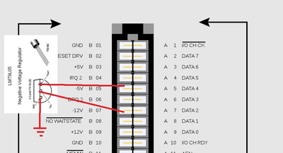
Easier to add 79L05 in TO-92 case to soundcard, and before this cutting -5V pin at ISA
TO-92 can be soldered into the holes along with the leads of the input capacitors.
If you do it carefully, it will not be noticeable at all

Attachments

  • 79l05.jpg
    Filename
    79l05.jpg
    File size
    51.62 KiB
    Views
    668 views
    File license
    Public domain

Aopen MX3S, PIII-S Tualatin 1133, Radeon 9800Pro@XT BIOS, Diamond monster sound MX300
JetWay K8T8AS, Athlon DH-E6 3000+, Radeon HD2600Pro AGP, Audigy 2 Value

Reply 38 of 39, by mkarcher

User metadata
Rank l33t
Rank
l33t
nathanieltolbert wrote on 2023-04-06, 19:53:

In regards to tacking on the caps to the back of the card, are there any potential issues or problems I might run into? I only ask because this isn't my card, and I don't want to destroy it.

I'm going to answer this, even though you already found out your issue isn't caused by the caps, for other readers in the future that might have similar questions:

Tacking caps in the back requires you to solder at the old joints. They don't have the patina of 30 year old joints anymore. If you don't clean the flux afterwards, the flux residues will also clearly tell that someone tinkered with the card, so it clearly degrades the untaintedness, which might impact the collector's value. The PAS16 is an uncommon item, so collector's value might be a relevant concern.

There is no concern about electrical functionality as long as you work carefully (i.e.: you don't create any accidental shorts, you tack on the caps respecting the polarity).

nathanieltolbert wrote on 2023-04-06, 19:53:

Also, the PSU I am using does indeed provide -5V. It's a NOS AT PSU.

In that case, my money is on a broken -5V trace from the AT connector to the ISA slots, or a broken solder joint at the AT connector. Problems like this are common after battery damage, so your suspicion seems to be correct.

Reply 39 of 39, by nathanieltolbert

User metadata
Rank Member
Rank
Member
mkarcher wrote on 2023-04-07, 07:24:

In that case, my money is on a broken -5V trace from the AT connector to the ISA slots, or a broken solder joint at the AT connector. Problems like this are common after battery damage, so your suspicion seems to be correct.

I'm pretty sure that I didn't get all of the battery leakage damage cleaned and corrected. This board is an odd duck as it is, and it still has some annoying issues I need to figure out how to fix. I have a dead one that I need to see if I can recover it. But the traces are super tiny.