VOGONS


First post, by anetanel

User metadata
Rank Member
Rank
Member

I have this DSP-1454NN AT PSU (branded as Compu Case YCC 200W) that I opened up to clean.
It used to work but I did not check it again before opening it up (mistake 1).
After cleaning and reassembling, I verified that there are no shorts on the main input leads that I had to resolder, but I did not check for shorts on the output rails (mistake 2).
When powered up (without any load), it started to spin the fan, but then the fuse blew.
So, before replacing the fuse, I finally checked the output rails, and noticed that there is very little resistance between the common (black) and the +5v (red) rail.
The resistance between the rails is low and gradually increases up to about 113 ohm after couple of seconds.
A multimeter on continuity mode beeps for a second and then as the resistance grows a bit it stops beeping.

Is this behavior normal? If so, what could be the cause of the fuse blowing up?
What else should I check before replacing the fuse?

Many thanks 😀

Attachments

  • IMG_8004.jpg
    Filename
    IMG_8004.jpg
    File size
    715.74 KiB
    Views
    880 views
    File license
    Public domain
  • IMG_8006.jpg
    Filename
    IMG_8006.jpg
    File size
    832.87 KiB
    Views
    880 views
    File license
    Public domain
  • IMG_8002.jpg
    Filename
    IMG_8002.jpg
    File size
    700.46 KiB
    Views
    880 views
    File license
    Public domain
  • IMG_8001.jpg
    Filename
    IMG_8001.jpg
    File size
    788.07 KiB
    Views
    880 views
    File license
    Public domain

Reply 2 of 41, by anetanel

User metadata
Rank Member
Rank
Member
bogdanpaulb wrote on 2023-03-19, 16:27:

Did you check the input voltage selector ?

Do you mean the 115v/230v switch?
It is actually wired so only the 230v state is active...
The 115v side is not wired at all.

Attachments

  • IMG_8007.jpg
    Filename
    IMG_8007.jpg
    File size
    650.63 KiB
    Views
    863 views
    File license
    Public domain

Reply 4 of 41, by anetanel

User metadata
Rank Member
Rank
Member
anetanel wrote on 2023-03-19, 16:34:
Do you mean the 115v/230v switch? It is actually wired so only the 230v state is active... The 115v side is not wired at all. […]
Show full quote
bogdanpaulb wrote on 2023-03-19, 16:27:

Did you check the input voltage selector ?

Do you mean the 115v/230v switch?
It is actually wired so only the 230v state is active...
The 115v side is not wired at all.

I may (who am I kidding.. surly) not understand how this switch actually work.
After further inspection, it seems that when in the 230v state, both wires are shorted to the neutral main input (blue). one (white) wire goes to a via on the board marked A, and the second (black) wire to a via marked B.
When on the 115v state, only the white wire is "hot".
So I guess that means that when in 115v only half of the voltage(?) is used?

Anyway, I guess this switch is OK?

Reply 5 of 41, by anetanel

User metadata
Rank Member
Rank
Member
bogdanpaulb wrote on 2023-03-19, 16:54:

That's exactly the way it works , shorting the 2 wires for one voltage and breaking the circuit for the other. Is it in the correct position ?

🤣 😀
yes. It is on 230v as it should be where I am.

Reply 6 of 41, by bogdanpaulb

User metadata
Rank Member
Rank
Member
anetanel wrote on 2023-03-19, 14:26:

So, before replacing the fuse, I finally checked the output rails, and noticed that there is very little resistance between the common (black) and the +5v (red) rail.
The resistance between the rails is low and gradually increases up to about 113 ohm after couple of seconds.
A multimeter on continuity mode beeps for a second and then as the resistance grows a bit it stops beeping.

That sounds good for the 5v rail , you are basically measuring fast rectifiers(in parallel) in parallel with filtering caps. Change the polarity of the multimeter leads when you measure, it should gradually increase and not stop at ~113.

Reply 7 of 41, by anetanel

User metadata
Rank Member
Rank
Member
bogdanpaulb wrote on 2023-03-19, 19:54:
anetanel wrote on 2023-03-19, 14:26:

So, before replacing the fuse, I finally checked the output rails, and noticed that there is very little resistance between the common (black) and the +5v (red) rail.
The resistance between the rails is low and gradually increases up to about 113 ohm after couple of seconds.
A multimeter on continuity mode beeps for a second and then as the resistance grows a bit it stops beeping.

That sounds good for the 5v rail , you are basically measuring fast rectifiers(in parallel) in parallel with filtering caps. Change the polarity of the multimeter leads when you measure, it should gradually increase and not stop at ~113.

I tried that now, but it seems to hold at 113ohm either way.
I'll get some new fuses tomorrow and try to replace the blown one.
Anything to check before that?

Reply 9 of 41, by Deunan

User metadata
Rank Oldbie
Rank
Oldbie
anetanel wrote on 2023-03-19, 14:26:

Is this behavior normal? If so, what could be the cause of the fuse blowing up?
What else should I check before replacing the fuse?

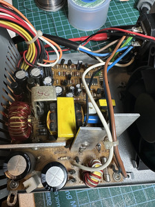
PC PSU should not be blowing fuses. Some are poorly designed but in general a short on output should trip it safely, so you have an issue there. Things that come to mind:
1) loss of control, which can be due to some caps filtering power for the PWM chip going dry/open
2) badly unformed input capacitors
3) shorted input rectifier diode (just one of them - just test them)

Shorted switching transistor usually explode and take out the rectifier with it, and that's easy to find by checking for dead shorts on their pins. Could be it died after a second but in general when they go it's right away (so there wouldn't be fan spin at all) and there are some nice sound/visual/smell effects. So I don't think it's that but as I've said, easy to check.

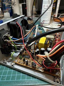
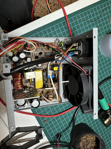
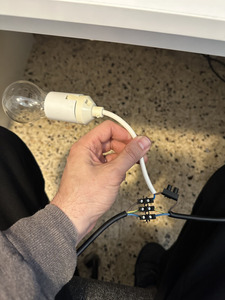
So, (1) could be also caused (in poor designs) by too little load. Get two car lightbulbs, 21W 12V each, connect one to 12V line, the other to 5V line. That will provide safe and cheap (and disposable in case of overvoltage) load.
(2) can be easily cured by letting the caps reform in a safe, slow way - connect 60W 230V bulb in series with the line cord. That bulb should briefly light up and then go dark when the PSU is powered on. A faint glow with the 2x 21W load is also possible but if you get nice, bright light that doesn't go away I'd say there is a short on the primary somewhere or rather catastrophic loss of regulation. Repairs needed.
If the 230W bulb is kinda slow to get dim but does get dimmer over a time of a minute or so, it might just be the capacitors reforming. It should get dark in 30s or less, if not the caps need replacing, I wouldn't trust them. And you might want to give the PSU 24h rest and repeat that, the caps should stay well formed over that time. If there's slow dimming again, replace caps.

The input lightbulb will also save you from having to replace the fuse again, it'll take the load, although if something is shorted in the PSU it might get hot or start smoking after a while. So don't leave it unattended if the bulb is not getting dim/dark right away. Don't let it shine brightly more than 20s, if it's not going dark disconnect power and investigate what (if anything) is getting hot.

Reply 10 of 41, by anetanel

User metadata
Rank Member
Rank
Member
Deunan wrote on 2023-03-19, 22:59:

(2) can be easily cured by letting the caps reform in a safe, slow way - connect 60W 230V bulb in series with the line cord. That bulb should briefly light up and then go dark when the PSU is powered on.

Can you elaborate on that?
Where do I need to connect the bulb? on the main cable?
This PSU has an output for connecting a monitor, can I use it to attach the bulb?
I'm always getting confused when "series" and "parallel" are involved in real life circuits .

Reply 11 of 41, by Deunan

User metadata
Rank Oldbie
Rank
Oldbie
anetanel wrote on 2023-03-21, 12:19:

Can you elaborate on that?
Where do I need to connect the bulb? on the main cable?
This PSU has an output for connecting a monitor, can I use it to attach the bulb?

Yes, on the mains cable. Assuming L is live and N is neutral (although it doesn't matter if it's in reverse):
* Wall socket L -> cable -> 60W lightbulb -> cable -> PSU
* Wall socket N -> cable -> PSU
* Wall socket PE -> cable -> PSU

Do not mess with PE (protective earth) at any time, but one of the L/N connections must go through a lighbulb. You can cut/mod some old extension cord for that for example. You will need a fixture for the bulb but it doesn't need to be anything permanent for one PSU repair, just follow the common sense (no bare wires, bulb not touching anything flammable, etc).

No, you can't use the the output on the PSU to attach the bulb, unless you want just an extra light - which is not the point. Lightbulb in this case acts as a current limiter, indicator, and safe dummy load in case of a short. That's why it needs to be some 60W at least - you could probably get away with 40 or even 25 watts for a PSU with no load, but I did mention that no load might be the problem. So 60 or 75 (or even 100W if that's all you have on hand) and some light load for the secondary is the best way to test. With such light load, and reasonable PSU efficiency, the 60W lightbulb would be at most barely lit, preferably dark. Brightly lit = PSU pulling too much current, needs investigating.

Reply 12 of 41, by anetanel

User metadata
Rank Member
Rank
Member
Deunan wrote on 2023-03-21, 12:49:

* Wall socket L -> cable -> 60W lightbulb -> cable -> PSU

so both wires of the bulb socket go on the same line?

Attachments

  • IMG_8010.jpg
    Filename
    IMG_8010.jpg
    File size
    679.13 KiB
    Views
    697 views
    File license
    Public domain

Reply 14 of 41, by anetanel

User metadata
Rank Member
Rank
Member

So with the 12v bulbs as load on 12v an 5v rails, the 60W bulb runs bright and does not dim at all 🙁
The 12v bulbs don't light at all.
I couldn't find anything super hot yet.. at least not for the amount of time i dared to let it run...

Reply 15 of 41, by Deunan

User metadata
Rank Oldbie
Rank
Oldbie

That is most likely a short on the primary side then. Let the PSU sit disconnected for 5min then start checking things:
1) diodes D1, D2, D3 and D4 for being shorted, preferably using diode check function in the meter - anything below 0.5V is very suspicious since these are silicon diodes
2) both input capacitors for dead shorts
But be careful there, there are 100k bleed resistors to discharge those over time (that's why you wait), but these can go open or soldering cracked. If in doubt measure voltage across each cap first and don't touch anything holding charge (and keep in mind any human-safe voltage can still damage the meter, best to wait until those are below 1V)
3) switching transistor for shorts

Any shorts found at any of these steps require checking the rest too. It's rare for the transistor to short and diodes to survive for example.

Reply 16 of 41, by anetanel

User metadata
Rank Member
Rank
Member

Found short on diode D4. Took it out and it is indeed shorted on both sides. The other diodes beeped only on one side, and the other showed 0.55 (what are we measuring here actually?)

Large caps seem ok. No shorts.

On one of the transistors, all 3 legs were shorted. I took it out and it is ok. But the pads are all shorted though.
It seems that the medium size caps are also shorted...

Do you think that one of those medium caps is shorted and causing everything else to short too?

Reply 17 of 41, by shevalier

User metadata
Rank Member
Rank
Member
anetanel wrote on 2023-03-21, 19:02:

what are we measuring here actually?

Actualy, We measuring the voltage drop at a current of 10 mA (at range with "diod" and/or "beeper") .
For example, a 1N4148 diode.
The tester will show 800.
Only this is not 800 ohms, as it would seem.
This is 800 millivolts

Attachments

  • drop volt.jpg
    Filename
    drop volt.jpg
    File size
    31.66 KiB
    Views
    639 views
    File license
    Fair use/fair dealing exception

Aopen MX3S, PIII-S Tualatin 1133, Radeon 9800Pro@XT BIOS, Diamond monster sound MX300
JetWay K8T8AS, Athlon DH-E6 3000+, Radeon HD2600Pro AGP, Audigy 2 Value

Reply 18 of 41, by Deunan

User metadata
Rank Oldbie
Rank
Oldbie
anetanel wrote on 2023-03-21, 19:02:

Found short on diode D4. Took it out and it is indeed shorted on both sides. The other diodes beeped only on one side, and the other showed 0.55 (what are we measuring here actually?)

You are measuring forward voltage drop - diodes are not perfect, there is some drop (necessary for the semiconductor junction to work) and therefore dissipated heat (current through diode * voltage drop, that's ignoring dynamic effects).
That diode will need to be replaced. At least this one, you could replace all 4 to have them more or less matched but it's not critical on the primary side. Something rated at 2A average current and 500+ volts of blocking voltage. If you are going to be using this PSU at 115V then I'd suggest going for 3A to 4A diode - in general for 200W you could say 1A would be enough for 230V but you want to have some safety margin and also higher average current also means higher rating for the initial pulse (charging the capacitors).

anetanel wrote on 2023-03-21, 19:02:

On one of the transistors, all 3 legs were shorted. I took it out and it is ok. But the pads are all shorted though.
It seems that the medium size caps are also shorted...

I'm going to refer to your PCB photo (IMG_8006) - there's three parts on that PCB that have 3 leads. From left to right it's a double diode - most likely the 5V rectifier, then in the middle and right you have 2 transistors. Both should be of identical type. Remove both, replace the diode, repeat the 60W lightbulb test. You can skip the load, the PSU is not going to work without these transistors, but the point is to see if the short went away. And also it should give you a clue what the bulb should do (blink once on power on). Usually when one of these transistor fails, so does the other, but that's not always true. And the only sure way to test them is out of circuit.

These transistors are fully isolated from the secondary side by a pulse transformer (it's the smaller of the two in the PSU), and there are some parts (a few resistors, an electrolytic capactitor, perhaps a diode) to shape the turn on/off signals from the transformer to the base of the transistors. These are almost always NPN high pulse current, high breakdown voltage parts. The shaping parts, there's not much to go wrong with these and shorts are not going to cause a general short on primary side, it has to be the transistors themselves. There are 2 because it's a push-pull configuration.

It might be a good idea to replace the electrolytic capacitors in the base drive circuits, first because they could be the culprit (although usually it would degrade the PSU output, not cause it to kill the transitors) and second because they might have taken a pretty high voltage pulse and got damaged - even if they seem OK.

Reply 19 of 41, by anetanel

User metadata
Rank Member
Rank
Member

Got it.
Obviously if I had looked at the component I took out I would have seen that it is not a transistor, just by the pretty double diode picture on it 🤦🏻‍♂️.
I'll put it back and look for diodes and capacitors near by.
The faulty diode is a N5398, which is 1.5A/800V, if I read the sheet correctly. I'll try to find something similar and replace all 4.