First post, by sorrow
Hi,
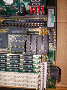
I'm repairing OPTI-495SLC 386 WB manboard: https://stason.org/TULARC/pc/motherboards/U/U … SLC-386-WB.html
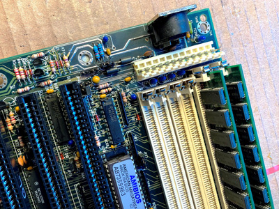
It has some damage due to battery leak that I have cleared. I measured affected wire patches and they seems to be OK. The damaged part is shown on the attached picture.
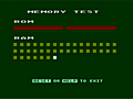
The board often fails to POST when I turn the PSU on. Most often POST card gives AMI BIOS 12/13 error codes but no code or different codes are also shown sometimes.
When I press reset button the board boots normally in 100% of cases.
I measured the PSU with multimeter and I also tried another PSU to exclude any issue there.
My guess is that some component on the board needs too much time (after power on) to start functioning properly but I lack experience to identify it
Any ideas what to do and where to start?
Jan