bogdanpaulb wrote on 2023-03-25, 13:35:
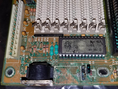
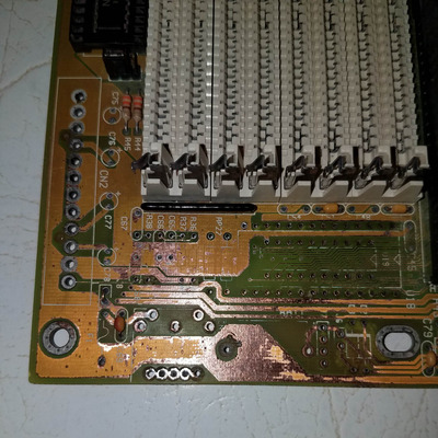
You don't need another board to restore it. If you look at the layout/traces, the caps you need the value for are all connected to ground (filtering/decoupling caps) c48 , c51 and c79 are all the same and you have the value on c79 in the first pic (104) 100nF (0.1uF). For c65,66,67,68 the same, you have c67 intact in the firs pic (what was the value on it?). D3 is used for reverse voltage protection for the battery and you can use almost any type of rectifier/switching diode in that package (you have in the first pic also, starts with 1N..). Don't forget about that damaged trace that leads to R38.
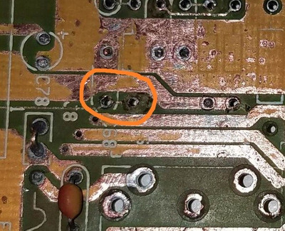
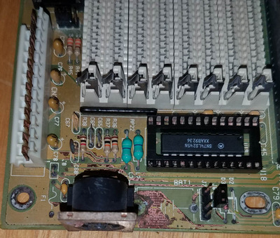
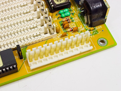
Thank you. Yes, I have not repaired traces yet, just cleaned it up and got stuff out of the way. Getting a mouser order ready, and will check all the traces and fix any at parts install. C67 was rougher than it looks. Here is a pic after first vinegar scrub down. I have some photos on my sons phone, he is still asleep, but of other angles but it didn't look ledgeable iirc.
Any reason not to use surface mount ceramics? I have some on hand already, but will buy the other style if it makes a difference.