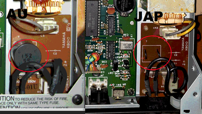
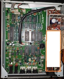
I cant find a 4x5v output transformer but, you can make a custom pcb to place it in that area, put the fuse under the power switch and the rest of the pcb use it to fit 2 pcb transformers like: one of 2x5v 3va for analog and one 2x5v 6va for digital. You have to measure and find 2 that will fit on that pcb. https://uk.rs-online.com/web/p/pcb-transformers/0504454 this is an example, so you can search something similar that is available in you area.
Or you can also make the pcb with the fuse much smaller and use the remaining space to fit 2 normal mounting transformers.
I see that the device is rated with 100ma for analog power so 2X5v, 2x0.5va should be minimum to be safe (100ma per output, 200ma total max power) and for the digital part is 400ma rated so you can go with a minimum of 2x5v, 2x2va (400ma per output, max 800 total power). This are the minimal ratings i recommend.
Here are some more examples :
https://ro.mouser.com/ProductDetail/Hammond-M … ntPdMG8oQ%3D%3D for analog
https://ro.mouser.com/ProductDetail/Hammond-M … z3qCfZqcQ%3D%3D for digital