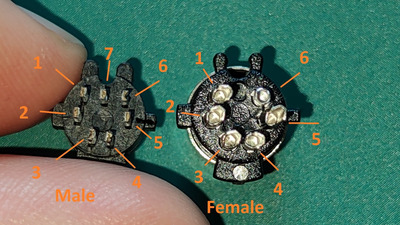
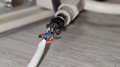
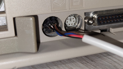
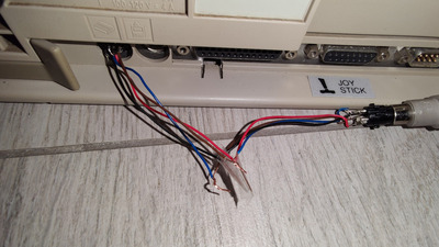
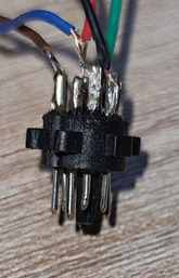
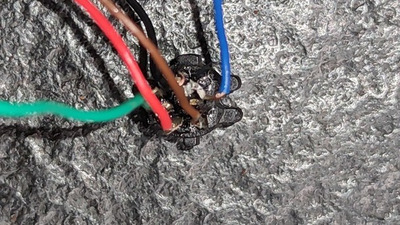
Red and black can be soldered permanently, you can use the 'on the way' method for the rest of the signals, clock and data. You didn't followed the instructions, i can see from the start that the red and black wire are not connected ok on the male minidin7 (plug that goes in to the computer). Use the picture with both connectors from the bottom of your sheet and this, nothing else:
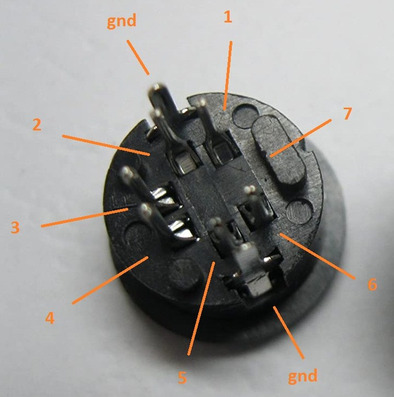
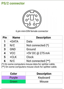
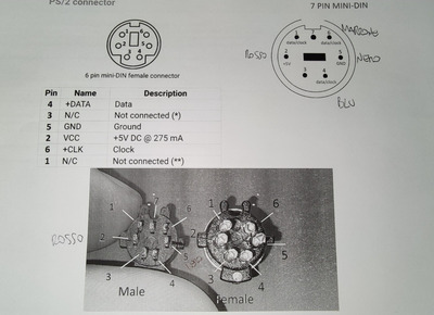
Here is the pin out assuming you are looking at BOTH CONNECTORS for the adapter from the soldering part of the pins. Pin 7 will exist only on the male minidin7 connector and it's unused as also some other pins.
- wire from pin 2 of the male minidin7 to pin 5 of the female minidin6, +5v dc, use red wire.
- wire from pin 5 of the male minidin7 to pin 2 of the female minidin6, gnd, use withe/black wire and you can solder the ground pins from the picture to it.
- wire from pin 4 of the male minidin7 to pin 3 of the female minidin6, data/clock signal, use green/yellow wire.
- wire from pin 6 of the male minidin7 to pin 1 of the female minidin6, data/clock signal, use green/yellow wire.
If it's not working, reverse the wires from pin 4 and pin 6 of the minidin6 female connector.
If still not working:
- remove wire from pin 4 of the male minidin7
- solder wire to pin 1 of the male minidin7
If it's not working, reverse the wires from pin 4 and pin 6 of the minidin6 female connector.
If still not working:
- remove wire from pin 6 of the male minidin7
- solder wire to pin 4 of the male minidin7
If it's not working, reverse the wires from pin 4 and pin 6 of the minidin6 female connector.
Don't forget to turn off/on the computer after each try, so the keyboard circuitry have a chance to initialize properly.