VOGONS


Reply 80 of 90, by weedeewee

User metadata
Rank l33t
Rank
l33t

Just wanted to add my 2eurocents...

Verify, lookup, check & recheck & verify again that the pinout you are using is correct.

for example, the photo you posted of the pinouts a few posts earlier.
The 6 pin mini-DIN Female connector pinout.
it's giving me a headache to think about it right now so I'll be off to bed soon.
anyway. the pinout description is looking at the connector from where you plug in the other connector. NOT from looking at the solder points.
Ergo
on the photo where you added the numbers to the ps2 connector 1=6 2=5 3=4
The sides are switched. you're putting 5v from the computer on the ground of the keyboard and putting the ground of the computer on the 5v line of the keyboard.

meh, read next comment. 😉

Last edited by weedeewee on 2023-08-14, 07:07. Edited 2 times in total.

Right to repair is fundamental. You own it, you're allowed to fix it.
How To Ask Questions The Smart Way
Do not ask Why !
https://www.vogonswiki.com/index.php/Serial_port
Reply 81 of 90, by mkarcher

User metadata
Rank l33t
Rank
l33t
weedeewee wrote on 2023-08-13, 19:07:

Verify, lookup, check & recheck & verify again that the pinout you are using is correct.

The sides are switched. you're putting 5v from the computer on the ground of the keyboard and putting the ground of the computer on the 5v line of the keyboard.

(I am that "Michael" who helped in the process) bogdanpaulb used an unconventional scheme of counting the pins from the solder side in counter-clockwise direction for both the female and the male plug, in an attempt to make soldering more easy. With the numbered photos, the connection schemes as written are correct and do not provide the supply voltage reversed. The keyboard actually powers up correctly, but in all six ways to connect the two keyboard lines (CLK/DATA) to the three lines that are near 5V (likely due to pullup) in the keyboard port, the POST stops at "Keyboard: Error 8".

Reply 82 of 90, by weedeewee

User metadata
Rank l33t
Rank
l33t
mkarcher wrote on 2023-08-13, 22:06:
weedeewee wrote on 2023-08-13, 19:07:

Verify, lookup, check & recheck & verify again that the pinout you are using is correct.

The sides are switched. you're putting 5v from the computer on the ground of the keyboard and putting the ground of the computer on the 5v line of the keyboard.

(I am that "Michael" who helped in the process) bogdanpaulb used an unconventional scheme of counting the pins from the solder side in counter-clockwise direction for both the female and the male plug, in an attempt to make soldering more easy. With the numbered photos, the connection schemes as written are correct and do not provide the supply voltage reversed. The keyboard actually powers up correctly, but in all six ways to connect the two keyboard lines (CLK/DATA) to the three lines that are near 5V (likely due to pullup) in the keyboard port, the POST stops at "Keyboard: Error 8".

So it's likely using a different protocol to communicate with the keyboard... ?
Is there any info available on those other DE-9 ollivetti keyboard connectors ?
edit: they only use 5 wires

Right to repair is fundamental. You own it, you're allowed to fix it.
How To Ask Questions The Smart Way
Do not ask Why !
https://www.vogonswiki.com/index.php/Serial_port
Reply 83 of 90, by biessea

User metadata
Rank Member
Rank
Member
weedeewee wrote on 2023-08-14, 07:09:
So it's likely using a different protocol to communicate with the keyboard... ? Is there any info available on those other DE-9 […]
Show full quote
mkarcher wrote on 2023-08-13, 22:06:
weedeewee wrote on 2023-08-13, 19:07:

Verify, lookup, check & recheck & verify again that the pinout you are using is correct.

The sides are switched. you're putting 5v from the computer on the ground of the keyboard and putting the ground of the computer on the 5v line of the keyboard.

(I am that "Michael" who helped in the process) bogdanpaulb used an unconventional scheme of counting the pins from the solder side in counter-clockwise direction for both the female and the male plug, in an attempt to make soldering more easy. With the numbered photos, the connection schemes as written are correct and do not provide the supply voltage reversed. The keyboard actually powers up correctly, but in all six ways to connect the two keyboard lines (CLK/DATA) to the three lines that are near 5V (likely due to pullup) in the keyboard port, the POST stops at "Keyboard: Error 8".

So it's likely using a different protocol to communicate with the keyboard... ?
Is there any info available on those other DE-9 ollivetti keyboard connectors ?
edit: they only use 5 wires

What's that DE-9 keyboard connectors? Is that a standard?

How can you know they use 5 wires? This is probably the cause I always received the error 8 keyboard error yet?
(i only connected four wires at time)

Computer lover since 1992.
Love retro-computing, retro-gaming, high-end systems and all about computer-tech.
Love beer, too.

Reply 84 of 90, by mkarcher

User metadata
Rank l33t
Rank
l33t
biessea wrote on 2023-08-14, 15:11:

What's that DE-9 keyboard connectors? Is that a standard?

DE-9 is the connector shape used by the small serial ports. See for example here: https://it.wikipedia.org/wiki/D-subminiature. The connector shape is standard. There is no standard for PC keyboards using a DE-9 plug, though.

biessea wrote on 2023-08-14, 15:11:

How can you know they use 5 wires? This is probably the cause I always received the error 8 keyboard error yet?
(i only connected four wires at time)

You only connected 4 wires at a time, because you used a PS/2-type keyboard. A PS/2-type keybord only has four pins connected in the mini-din plug, so connecting wires to the extra pins doesn't make sense.

Reply 85 of 90, by biessea

User metadata
Rank Member
Rank
Member
mkarcher wrote on 2023-08-14, 16:58:
DE-9 is the connector shape used by the small serial ports. See for example here: https://it.wikipedia.org/wiki/D-subminiature. […]
Show full quote
biessea wrote on 2023-08-14, 15:11:

What's that DE-9 keyboard connectors? Is that a standard?

DE-9 is the connector shape used by the small serial ports. See for example here: https://it.wikipedia.org/wiki/D-subminiature. The connector shape is standard. There is no standard for PC keyboards using a DE-9 plug, though.

biessea wrote on 2023-08-14, 15:11:

How can you know they use 5 wires? This is probably the cause I always received the error 8 keyboard error yet?
(i only connected four wires at time)

You only connected 4 wires at a time, because you used a PS/2-type keyboard. A PS/2-type keybord only has four pins connected in the mini-din plug, so connecting wires to the extra pins doesn't make sense.

All clear.

So we have to find other solutions I think.

Computer lover since 1992.
Love retro-computing, retro-gaming, high-end systems and all about computer-tech.
Love beer, too.

Reply 86 of 90, by weedeewee

User metadata
Rank l33t
Rank
l33t
biessea wrote on 2023-08-14, 15:11:
What's that DE-9 keyboard connectors? Is that a standard? […]
Show full quote
weedeewee wrote on 2023-08-14, 07:09:
So it's likely using a different protocol to communicate with the keyboard... ? Is there any info available on those other DE-9 […]
Show full quote
mkarcher wrote on 2023-08-13, 22:06:

(I am that "Michael" who helped in the process) bogdanpaulb used an unconventional scheme of counting the pins from the solder side in counter-clockwise direction for both the female and the male plug, in an attempt to make soldering more easy. With the numbered photos, the connection schemes as written are correct and do not provide the supply voltage reversed. The keyboard actually powers up correctly, but in all six ways to connect the two keyboard lines (CLK/DATA) to the three lines that are near 5V (likely due to pullup) in the keyboard port, the POST stops at "Keyboard: Error 8".

So it's likely using a different protocol to communicate with the keyboard... ?
Is there any info available on those other DE-9 ollivetti keyboard connectors ?
edit: they only use 5 wires

What's that DE-9 keyboard connectors? Is that a standard?

How can you know they use 5 wires? This is probably the cause I always received the error 8 keyboard error yet?
(i only connected four wires at time)

The one olivetti keyboard I've got laying around has such a DE-9 connector with only 5 wires connected. It's not a standard, but it was used on an olivetti m24, and likely some others as well.

Right to repair is fundamental. You own it, you're allowed to fix it.
How To Ask Questions The Smart Way
Do not ask Why !
https://www.vogonswiki.com/index.php/Serial_port
Reply 87 of 90, by biessea

User metadata
Rank Member
Rank
Member

Hey guys, finally we made it!

Thanks to Michael I passed a night to test on the mainboard and we found out that a pin in the ps2 connector was too out of the connector, cause soldering the plastic melt a bit and moved that pin that made no contact with the keyboard connector.

Today I adjusted this and finally we move over the keyboard error.
It's like a dream wow.

This is the correct pinout so at the end: (always see from the solder point and counter clockwise)

- pin 2 minidin7 to pin 5 ps2 connector (red cable +5v.)
- pin 4 mindin7 to pin 3 ps2 connector
- pin 5 minidin7 to pin 2 ps2 connector (black wire GND)
- pin 6 minidin7 to pin 1 ps2 connector.

Finally we have it.

Now I am experiencing problems with finding hard drive and floppy drive (this one I think I didn't pull all inside the flat cable or simply connected inverted).

Attachments

Computer lover since 1992.
Love retro-computing, retro-gaming, high-end systems and all about computer-tech.
Love beer, too.

Reply 88 of 90, by mkarcher

User metadata
Rank l33t
Rank
l33t
biessea wrote on 2023-08-15, 16:29:
This is the correct pinout so at the end: (always see from the solder point and counter clockwise) […]
Show full quote

This is the correct pinout so at the end: (always see from the solder point and counter clockwise)

- pin 2 minidin7 to pin 5 ps2 connector (red cable +5v.)
- pin 4 mindin7 to pin 3 ps2 connector
- pin 5 minidin7 to pin 2 ps2 connector (black wire GND)
- pin 6 minidin7 to pin 1 ps2 connector.

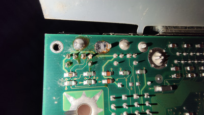
So, if we use the standard convention to count male and female connectors the opposite way, this is a 1:1 mapping. The minidin-7 in the PC was soldered by someone without the tool and/or skill to make nice-looking solder joints, but the connections were working. The PCB is meant for two 6-pin sockets. My guess is that someone replaced the 6-pin connector of the keyboard by a 7-pin connector to have mouse and keyboard keyed differently, so children toying around with the computer or old people with dementia couldn't accidentally swap keyboard and mouse, resulting in a non-working system.

Reply 89 of 90, by biessea

User metadata
Rank Member
Rank
Member
mkarcher wrote on 2023-08-16, 19:25:
biessea wrote on 2023-08-15, 16:29:
This is the correct pinout so at the end: (always see from the solder point and counter clockwise) […]
Show full quote

This is the correct pinout so at the end: (always see from the solder point and counter clockwise)

- pin 2 minidin7 to pin 5 ps2 connector (red cable +5v.)
- pin 4 mindin7 to pin 3 ps2 connector
- pin 5 minidin7 to pin 2 ps2 connector (black wire GND)
- pin 6 minidin7 to pin 1 ps2 connector.

So, if we use the standard convention to count male and female connectors the opposite way, this is a 1:1 mapping. The minidin-7 in the PC was soldered by someone without the tool and/or skill to make nice-looking solder joints, but the connections were working. The PCB is meant for two 6-pin sockets. My guess is that someone replaced the 6-pin connector of the keyboard by a 7-pin connector to have mouse and keyboard keyed differently, so children toying around with the computer or old people with dementia couldn't accidentally swap keyboard and mouse, resulting in a non-working system.

Nice thought Michael.

Can really it be that way.

I put the photo of the PCB of the mainboard where is the solders joint modded by that man that make us crazy for some days.

Attachments

  • IMG_20230814_214239.jpg
    Filename
    IMG_20230814_214239.jpg
    File size
    1.02 MiB
    Views
    396 views
    File comment
    Soldered joints
    File license
    Public domain

Computer lover since 1992.
Love retro-computing, retro-gaming, high-end systems and all about computer-tech.
Love beer, too.

Reply 90 of 90, by biessea

User metadata
Rank Member
Rank
Member

Just an update.

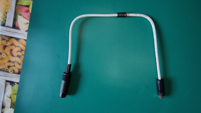
After days of struggling tying create this adaptor, finally I made it.

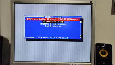
It works and now with a normal 3.5" floppy drive connected to the FDD connector on the mainboard, I finally managed to enter the bios.

I attach you some photos.

I will have to solder another CR2450 battery, this one obviously is GONE.

Attachments

  • 1693318496285.jpg
    Filename
    1693318496285.jpg
    File size
    134.06 KiB
    Views
    305 views
    File comment
    The adaptor made by me.
    File license
    Public domain
  • 1693318496141.jpg
    Filename
    1693318496141.jpg
    File size
    271.46 KiB
    Views
    305 views
    File comment
    entering the configuration program resident on a Floppy Disk
    File license
    Public domain
  • 1693318821841.jpg
    Filename
    1693318821841.jpg
    File size
    225.34 KiB
    Views
    305 views
    File comment
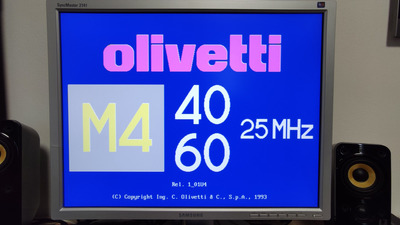
    beautiful boot screen
    File license
    Public domain
  • 1693318821862.jpg
    Filename
    1693318821862.jpg
    File size
    165.95 KiB
    Views
    305 views
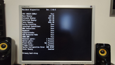
    File comment
    Boot informations
    File license
    Public domain
  • 1693318496164.jpg
    Filename
    1693318496164.jpg
    File size
    464.54 KiB
    Views
    305 views
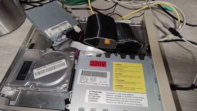
    File comment
    normal 3,5" flopy drive without the proprietary one with destroyed belt
    File license
    Public domain

Computer lover since 1992.
Love retro-computing, retro-gaming, high-end systems and all about computer-tech.
Love beer, too.