Reply 20 of 28, by GEOCE
Rank
Newbie
Yes, I have it, but I don't know where or what I have to measure. I'll take a picture of the board and send it to you when I get home.
Yes, I have it, but I don't know where or what I have to measure. I'll take a picture of the board and send it to you when I get home.
I suggest starting with a blow of canned air on the sensors (not the heads), and cleaning the data cable connector very well with alcohol. After that, turn on the PC and try to access a disk in the drive while slowly and lightly wiggling the data cable connection at the drive, see if suddenly the disk starts spinning.
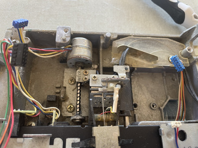
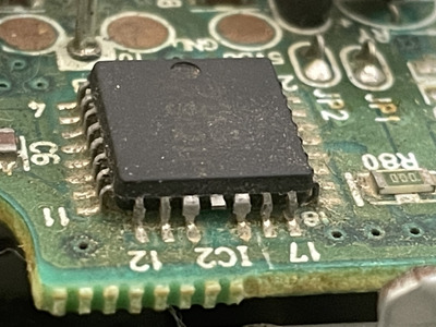
Motor not turning could mean disk is not detected in the drive, so it won't turn motor. If disk is not detected then the disk insertion sensor is off.. so probably a PCB issue (sad). That drive looks like a Panasonic to me. But yeah, you might have to take off the two PCBs and check them, which means full disassembly.. not nice, and I hope you can avoid it.
Good luck!
GEOCE wrote on 2023-05-05, 10:36:Yes, I have it, but I don't know where or what I have to measure. I'll take a picture of the board and send it to you when I get home.
So first a correction, I mean the blue connector with 5 wires (to reconnect), not the black one. These wires go to the spindle motor PCB and out of the 5 there should be: GND (ground), +5V, +12V, two control signals. So with an ohm meter check, directly from main PCB power connector to the wire soldering points on the motor PCB, if you have a good continuity for GND, 5V and 12V. Preferably don't use the "beep" function but actually measure resistance, for these 3 you should find a connection that is below 1 ohm.
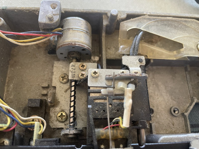
If there is a good connection for all 3 power lines that leaves you with the control signal not being passed or some possible damage on either PCB. You did not make a good photo of the motor PCB and these can sometimes suffer from capacitor spillage. BTW do not try to remove the motor PCB just yet - usually it can only be done from the top (3 screws) and first you need to know what you can safely remove without affecting head calibration.
So clean first, if that doesn't help measure the resistance of the power delivery wires and report back.
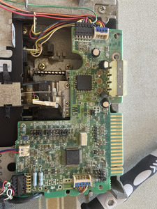
I found a little bit of acid behind the board, but I don't see anything stained underneath it
I don't understand much, and I don't know what those two components are, but one of them is showing that and the one I marked in red is not showing anything and stays at 1. Is that correct? Shouldn't both components give the same reading?
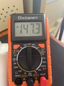
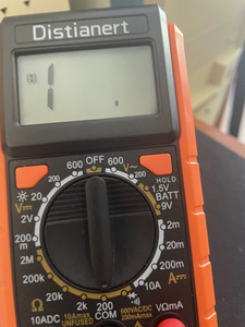
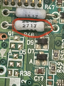
Sorry, I was measuring it wrong. Both components are working, and the voltages seem correct. Could the acid be from the capacitors that are not working properly? How can I tell?
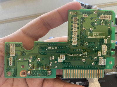
The brown stuff on the bottom of the main PCB is flux - should be removed by manufacturer but frankly many rosin based ones are not very acidic (and not really reactive at room temperature) so it can stay. But since you have the PCB fully removed please clean it with running water and soap. Use a mild brush to scrub, nothing abrasive. Make sure to rinse all the soap and let it dry. It'll take at least a day to dry at 20C, please do not try to rush it in any way - and sort of "baking" to speed up drying is usually a bad idea.
Once it looks dry (a few hours, but there will be trapped water under some parts still) please make another photo of the top side. And make a photo of the motor PCB while at it, to make sure the is no surface corrosion there.
I use canned air to blow out any extra water from under ic's, between parts, etc when I do a wash. Helps make sure no rust develops on any steel pins.
Hate posting a reply and then have to edit it because it made no sense 😁 First computer was an IBM 3270 workstation with CGA monitor. Stuff: https://archive.org/details/@horun
Ok thank you so much!! ❤️
I will do it and keep you updated

