VOGONS


First post, by crapasanya

User metadata
Rank Newbie
Rank
Newbie

I recently bought a motherboard to replace my broken one for my Packard Bell retro computer. At first I thought that it was fully functional until I connected a fresh 3V RTC (CMOS) battery, as written in the manual. I must say right away that the 4.5V battery did not improved the situation, it did not make any difference at all. I checked the polarity twice (in the instructions and by checking contiuity to the contacts of place for onboard lithium 3V battery before connecting the external (also lithium 3V) battery.

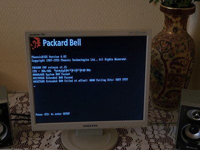
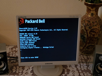
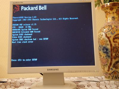
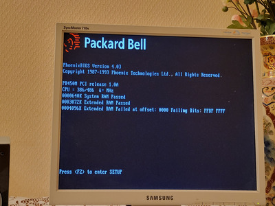
So, the problem itself: when working without a CMOS battery or at the first start until the power is COMPLETELY turned off (using the 220v button power supply), everything works fine: the system boots and all functions work, BIOS settings are saved (only hard drives do not work, but there are suspicions about the hard drives themselves, since only 1 out of 4 is known good). But as soon as you puwer off system for a second or more, the POST lasts more than 10 seconds (at a norm of 2-3) and after that the computer incorrectly determines the type of processor (386/486 instead of DX2-50), its frequency (there are meaningless characters with random-looking pseudographics) and the amount of RAM is multiplied: 4mb becomes 8mb, of which 4mb are "faulty", 19mb becomes 51mb, of which 32mb if "faulty", and 36mb becomes 100mb, of which 64mb are "faulty". Ant of course it dont't boot. And so it continues until the CMOS is reset by disconnecting the battery off the powered off device.

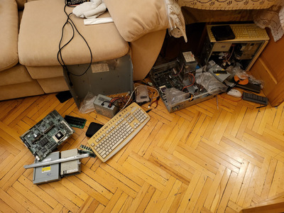
What has been done: the memory has been replaced, the built-in memory has been turned off, the processor has been replaced twice (DX2-50, DX2-66, DX-25), 3V lithium battery replaced with 4.5V (3x AAA), all expansion boards and drives unplugged.

Any ideas what it can be? I suspect that the chipset is partially dead, am I right? Or could this behavior just be due to a misconfiguration or old BIOS? Let me remind you that I have a donor that does not pass POST (as far as I remember, it cannot determine the amount of RAM). I also have a pretty good working place for soldering and some skill so i can replace almost anything on this board.

Attachments

Reply 1 of 18, by bregolin

User metadata
Rank Member
Rank
Member

Can you try using the BIOS ROM from the other board into this one? Wonder if the BIOS is corrupted or the ROM chip somehow damaged. Have you checked if the traces from the battery to the BIOS are good?

IBM Aptiva 2162 - P55 166 MMX, 32MB, CS4237B + Wavetable, ATI Mach64 2MB / Win98SE
Custom PIII 750, 64MB, SB AWE64, Voodoo 3 3000 AGP / Win98SE
Sony Vaio z505 SuperSlim - PIII 550, 192MB, YMF744, NeoMagic 256AV+ / Win98SE

Reply 2 of 18, by crapasanya

User metadata
Rank Newbie
Rank
Newbie
bregolin wrote on 2023-05-23, 13:26:

Can you try using the BIOS ROM from the other board into this one? Wonder if the BIOS is corrupted or the ROM chip somehow damaged. Have you checked if the traces from the battery to the BIOS are good?

Thanks, I also thought about the BIOS. I'll check out it and battery trades in a couple of hours when I get home. I also found the DRAM Parity switch in the manual, should I pay attention to it?

Reply 3 of 18, by Thermalwrong

User metadata
Rank Oldbie
Rank
Oldbie

Huh, I had that 386/486 mess of characters thing when I was playing about with feeding the CPU voltage from an external regulator. I thought I'd messed up the computer but clearing the CMOS got it back to working normally.

How do you have the RTC battery connected. Is it going to the pins where the original rechargeable battery was, or into the 4 pin external battery header?

Reply 4 of 18, by crapasanya

User metadata
Rank Newbie
Rank
Newbie
Thermalwrong wrote on 2023-05-23, 15:10:

Huh, I had that 386/486 mess of characters thing when I was playing about with feeding the CPU voltage from an external regulator. I thought I'd messed up the computer but clearing the CMOS got it back to working normally.

How do you have the RTC battery connected. Is it going to the pins where the original rechargeable battery was, or into the 4 pin external battery header?

Thanks for your reply. It is connected to a 4 pin connector.Sould i connect it in place of the onboard battery? I'll also try another power supply

Reply 5 of 18, by crapasanya

User metadata
Rank Newbie
Rank
Newbie
Thermalwrong wrote on 2023-05-23, 15:10:

Huh, I had that 386/486 mess of characters thing when I was playing about with feeding the CPU voltage from an external regulator. I thought I'd messed up the computer but clearing the CMOS got it back to working normally.

How do you have the RTC battery connected. Is it going to the pins where the original rechargeable battery was, or into the 4 pin external battery header?

So I tried ECC memory (with DRAM parity enabled), different power supply, different bios chip and checked battery tracks. Nothing helped, but: the other bios chip turned out to be PCI 1.0 version (instead of 1.15 without PCI) for the version with a PCI riser, and with it the meaningless characters disappeared, but the board just hung before detecting the drives. As a result, I returned the chip back, put the jumpers correctly and got not 386/486 and a lot of characters, but "DX2-66 (2 random characters)MHz" I also sometimes get a Real Time Clock error, which is quite important in this case, I think. When I have a rest, I'll try to measure the crystal oscillators on the board with an oscilloscope.

I also tried the second board: it sees the lack of memory (1-3-4-1 beep code), but when it is installed, it does not boot. And I just can't find the ISA post card. And, by the way, a few years ago it was flooded with dirty water, which conducts electricity a bit, but six months ago I washed it pretty well. I found some places that weren't fully cleaned, but there's no way to clean them right now.

Reply 6 of 18, by crapasanya

User metadata
Rank Newbie
Rank
Newbie

I forgot to attach photos

Attachments

Reply 7 of 18, by Thermalwrong

User metadata
Rank Oldbie
Rank
Oldbie
crapasanya wrote on 2023-05-23, 15:46:
Thermalwrong wrote on 2023-05-23, 15:10:

Huh, I had that 386/486 mess of characters thing when I was playing about with feeding the CPU voltage from an external regulator. I thought I'd messed up the computer but clearing the CMOS got it back to working normally.

How do you have the RTC battery connected. Is it going to the pins where the original rechargeable battery was, or into the 4 pin external battery header?

Thanks for your reply. It is connected to a 4 pin connector.Sould i connect it in place of the onboard battery? I'll also try another power supply

Nah that looks good, I use the external battery header too. The only reason I asked was because the on-board battery might get charged up while the external won't, so something like a CR2032 is best on the external battery connector.

Thanks for adding the pictures - I've never seen those type of ZIP memory expansions before for the VGA. Have you tested with/without those or do they otherwise work?

Reply 8 of 18, by Horun

User metadata
Rank l33t++
Rank
l33t++

Yeah those are non-standard ZIP memory upgrades for PB AFAIK, doubt that would effect boot up but never know.

Hate posting a reply and then have to edit it because it made no sense 😁 First computer was an IBM 3270 workstation with CGA monitor. Stuff: https://archive.org/details/@horun

Reply 9 of 18, by crapasanya

User metadata
Rank Newbie
Rank
Newbie
Thermalwrong wrote on 2023-05-24, 00:52:
crapasanya wrote on 2023-05-23, 15:46:
Thermalwrong wrote on 2023-05-23, 15:10:

Huh, I had that 386/486 mess of characters thing when I was playing about with feeding the CPU voltage from an external regulator. I thought I'd messed up the computer but clearing the CMOS got it back to working normally.

How do you have the RTC battery connected. Is it going to the pins where the original rechargeable battery was, or into the 4 pin external battery header?

Thanks for your reply. It is connected to a 4 pin connector.Sould i connect it in place of the onboard battery? I'll also try another power supply

Nah that looks good, I use the external battery header too. The only reason I asked was because the on-board battery might get charged up while the external won't, so something like a CR2032 is best on the external battery connector.

Thanks for adding the pictures - I've never seen those type of ZIP memory expansions before for the VGA. Have you tested with/without those or do they otherwise work?

Yes, I checked without them, zero difference. I'm most suspicious of the OPTi chipset chip right now, but first I'll check the crystal oscillators with an oscilloscope. I also found a postcard - let's see which post code everything hangs on. By the way, can the cache be the cause of this behavior? I think this is the only thing I haven't tested yet. But I turned it off in BIOS and it didn't help.

Reply 10 of 18, by crapasanya

User metadata
Rank Newbie
Rank
Newbie
bregolin wrote on 2023-05-23, 13:26:

Can you try using the BIOS ROM from the other board into this one? Wonder if the BIOS is corrupted or the ROM chip somehow damaged. Have you checked if the traces from the battery to the BIOS are good?

I've checked what you asked in one of upper messages

Reply 11 of 18, by crapasanya

User metadata
Rank Newbie
Rank
Newbie
Thermalwrong wrote on 2023-05-24, 00:52:
crapasanya wrote on 2023-05-23, 15:46:
Thermalwrong wrote on 2023-05-23, 15:10:

Huh, I had that 386/486 mess of characters thing when I was playing about with feeding the CPU voltage from an external regulator. I thought I'd messed up the computer but clearing the CMOS got it back to working normally.

How do you have the RTC battery connected. Is it going to the pins where the original rechargeable battery was, or into the 4 pin external battery header?

Thanks for your reply. It is connected to a 4 pin connector.Sould i connect it in place of the onboard battery? I'll also try another power supply

Nah that looks good, I use the external battery header too. The only reason I asked was because the on-board battery might get charged up while the external won't, so something like a CR2032 is best on the external battery connector.

Thanks for adding the pictures - I've never seen those type of ZIP memory expansions before for the VGA. Have you tested with/without those or do they otherwise work?

I found a postcard and this is what it shows: during a long POST, it hangs at 38 (3A is the previous one), when it hangs after it before the disks are allocated, it hangs at the d2 code (68 is the previous one), then after 5- 10 seconds the CE postcode appears (d2 is the previous one), then the system freezes completely. By the way, I get strange behavior on the oscilloscope from the crystal oscillator near the IDE connector: random (at least at the first glance) smooth voltage surges. Maybe I'm just measuring wrong?

I tried a motherboard without cache, with a different cache, and all 4 variations of the cache and its settings (old cache + 128k setting, new cache + 128k setting, old cache + 512k setting, new cache + 512k setting) - no difference.

I also connected the postcard to the donor - it is in a cycle between several postcodes. I have no idea at all what the reason is, so I'm attaching a video of what is happening. Maybe we should switch to it? I don't care which board will work.

Attachments

Last edited by crapasanya on 2023-05-24, 16:17. Edited 1 time in total.

Reply 12 of 18, by crapasanya

User metadata
Rank Newbie
Rank
Newbie

By the way, I found that the RTC is located right in the chipset. So far the most obvious option for me is to replace the chipset, but this is the most difficult element to replace on this board, so I don't want to rush into it.

Reply 13 of 18, by crapasanya

User metadata
Rank Newbie
Rank
Newbie

I tried to clean the board more thoroughly from dust - no result.
By the way, I forgot to write what the post codes mean: d2 is unknown interrupt error (Calling the interrupt handling procedure from an unidentified source), CE is displaying messages on the screen and initializing the digitizer

Reply 14 of 18, by bogdanpaulb

User metadata
Rank Member
Rank
Member

Have you tried to write a rom for the ISA riser version in to a new/different ic? or try with the pci riser version bios chip, but with the ide controller mapped to ISA(from the bios)? At 'fresh/cold' start, if you enter the bios and leave the pc like that for ~30 minutes, does it hang? Is the clock working ok? if so then the 32.768 khz crystal is used for RTC in combination with the 82c602 http://www.bitsavers.org/components/opti/data … ices_199411.pdf and it should be ok and not be the cause of your problem.

Reply 15 of 18, by crapasanya

User metadata
Rank Newbie
Rank
Newbie
bogdanpaulb wrote on 2023-05-24, 19:55:

Have you tried to write a rom for the ISA riser version in to a new/different ic? or try with the pci riser version bios chip, but with the ide controller mapped to ISA(from the bios)? At 'fresh/cold' start, if you enter the bios and leave the pc like that for ~30 minutes, does it hang? Is the clock working ok? if so then the 32.768 khz crystal is used for RTC in combination with the 82c602 http://www.bitsavers.org/components/opti/data … ices_199411.pdf and it should be ok and not be the cause of your problem.

Thanks for the answer. No, I just swapped the chips around. The donor board I swapped chip from was once working with a PCI bios and an ISA riser (so it should work), but then it flooded and was left like that for several years. And, although there are no noticeable oxides, this conductive rubbish still remains on it in inconspicuous places. I plan to buy myself an ultrasonic bath or ask to use one in the service

Reply 16 of 18, by bogdanpaulb

User metadata
Rank Member
Rank
Member
crapasanya wrote on 2023-05-26, 15:08:
bogdanpaulb wrote on 2023-05-24, 19:55:

Have you tried to write a rom for the ISA riser version in to a new/different ic? or try with the pci riser version bios chip, but with the ide controller mapped to ISA(from the bios)? At 'fresh/cold' start, if you enter the bios and leave the pc like that for ~30 minutes, does it hang? Is the clock working ok? if so then the 32.768 khz crystal is used for RTC in combination with the 82c602 http://www.bitsavers.org/components/opti/data … ices_199411.pdf and it should be ok and not be the cause of your problem.

Thanks for the answer. No, I just swapped the chips around. The donor board I swapped chip from was once working with a PCI bios and an ISA riser (so it should work), but then it flooded and was left like that for several years. And, although there are no noticeable oxides, this conductive rubbish still remains on it in inconspicuous places. I plan to buy myself an ultrasonic bath or ask to use one in the service

This is what i meant: you said that with the other bios chip, it hangs at ide detection, some motherboards have in bios the option to change the irq or map the integrated ide controller to the PCI bus or the ISA bus, so you can enter the bios before ide detection and try to change the irq or map the ide controller to the ISA bus if you have the options.

Attachments

  • ide controller1.jpg
    Filename
    ide controller1.jpg
    File size
    149.93 KiB
    Views
    765 views
    File license
    Fair use/fair dealing exception

Reply 17 of 18, by crapasanya

User metadata
Rank Newbie
Rank
Newbie
bogdanpaulb wrote on 2023-05-26, 17:12:
crapasanya wrote on 2023-05-26, 15:08:
bogdanpaulb wrote on 2023-05-24, 19:55:

Have you tried to write a rom for the ISA riser version in to a new/different ic? or try with the pci riser version bios chip, but with the ide controller mapped to ISA(from the bios)? At 'fresh/cold' start, if you enter the bios and leave the pc like that for ~30 minutes, does it hang? Is the clock working ok? if so then the 32.768 khz crystal is used for RTC in combination with the 82c602 http://www.bitsavers.org/components/opti/data … ices_199411.pdf and it should be ok and not be the cause of your problem.

Thanks for the answer. No, I just swapped the chips around. The donor board I swapped chip from was once working with a PCI bios and an ISA riser (so it should work), but then it flooded and was left like that for several years. And, although there are no noticeable oxides, this conductive rubbish still remains on it in inconspicuous places. I plan to buy myself an ultrasonic bath or ask to use one in the service

This is what i meant: you said that with the other bios chip, it hangs at ide detection, some motherboards have in bios the option to change the irq or map the integrated ide controller to the PCI bus or the ISA bus, so you can enter the bios before ide detection and try to change the irq or map the ide controller to the ISA bus if you have the options.

Strange. I don't know what happened, but now with the PCI BIOS it hangs on the first reboot with the battery connected at post code 68 (66 is the previous one) with a black screen, and after a time I get 2 meaningless characters and memory errors. Also, I found only the ability to disable the ide and floppy controller, but they are not saved without a battery, and with battery I can not get into the bios at all. By the way, there may have been a misunderstanding: both BIOSes hung before the IDE detection, but on the postcode D2 (unknown interrupt) or 68 (previous before D2, which means the enabling of external and CPU caches).

Attachments

Reply 18 of 18, by crapasanya

User metadata
Rank Newbie
Rank
Newbie

Thank you all very much for your help. Here's the happy ending: it turned out that the board needs a special battery with a special voltage (around 3.7v), and plus has to be connected to the plus of the built-in battery and minus to the ground (NOT the negative battery contact), in my case i just connected it to case. A regular 18650 li-ion battery works perfectly here.

Finally this PC was completely disassebled and cleaned (even the power supply, CD drive and floppy). Now the case went to a retrobrite (it lay near the window for a long time, so it was not even yellow, but orange), the PC is mostly assembled and I already play on it from time to time. I am happy, another PC of my childhood has been restored.

Attachments