jakethompson1 wrote on 2023-09-04, 07:43:
I have a board that does not have a documented EXT BATT header. But I believe the following CLR CMOS jumper doubles as an EXT BATT header.
Yes, this is correct.
jakethompson1 wrote on 2023-09-04, 07:43:
It appears safe to use this as an EXT BATT header as-is by removing the jumper on pins 2-3 and instead connecting a 3xAA battery pack across pins 1 and 4, is that correct?
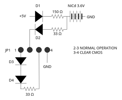
The only purpose of D3 and D4 is to drop voltage? Or is there some chance of power being back-fed to the primary battery even when the connection between pins 2 and 3 is broken, isolating it from the NiCd charging circuit?
I haven't traced pin 3 but I can only assume it goes to the appropriate RTC power pin on the chipset (this board doesn't use a discrete RTC).
The two diodes in series are definitely to drop the voltage. For all other purposes, a single diode would do as well. These diodes are not related to the NiCd charging circuit, as that circuit connects only to pin 2, which is left unconnected when you use an external battery. Your diagram does not include another vital component: There will be one or two diodes between +5V and pin 3 of the EXT BATT connector, to power the RTC from the AT power supply while the computer is turned on. The point of the D3/D4 (except for dropping voltage) is to prevent charging the external battery via this path, just as there is D2 which prevents charging the NiCD battery bypassing the 150 Ohm resistor. The "extra drop" with the two diodes most likely adjust from the 4.5V nominal AA battery voltage to the 3.6V NiCd battery pack voltage. It might also be there so you can connect a 4*AA battery pack or 2*CR123 (6V nominal voltage) without exceeding 5V on the output.
Some boards are specified to 4.5V on that connector, others are specified to take 6V.
jakethompson1 wrote on 2023-09-04, 07:43:
I can't read any identification on the diodes, but appears a typical diode in this circuit would drop the voltage by about 0.7V?
Yeah. Unless proven otherwise, just assume those diodes are 1N4148 or diodes with nearly identical characteristics.
jakethompson1 wrote on 2023-09-04, 07:43:
Is this a NiCd charging circuit with a constant current of 1000*4.3V/150Ω = 29 mA? Isn't that high if these batteries were only 60 mAh?
That would be extremely high. The barrel batteries are not optimized for fast charging, and charging them at C/2 without any kind of charge control would kill them within months of operating the computer, making the clock to fail within the warranty period. Your calculation is wrong. While you are correct that the voltage at the node between D1 and the 150 Ohm resistor will be about 4.3V (at low currents, better assume 0.6V, so make this 4.4V), the other end of the resistor is not at ground. During charging of a NiCd barrel, you can assume a per-cell voltage of 1.3V to 1.35V. The battery of 3 cells thus will be around 4V, and the voltage across the resistor will be 4.4V - 4.0V ~ 0.4V instead of the 4.3V you assumed. So the charge current is around 2.6mA, which is just below C/20. This in fact is the recommended "continous trickle charging circuit" for NiCd cells, so the charging circuit is mostly fine.
jakethompson1 wrote on 2023-09-04, 07:43:
[*]If I have trouble with boards providing EXT BATT maintaining settings, but not advancing the clock when a 3V CR2032 instead of a 4.5V 3xAA is used, is it safe to remove D1 and D2 and then bypass one or both of D3 and D4?[/list]
No need to remove D1 and D2. Pin 2 is a dead end when you remove the jumper 2-3 on that connector. Short/bypass only one of D3 or D4, so you still get charging prevention, but cut the drop in half might be the easiest solution to accept 3.0V at the EXT BATT connector (battery still connected to 1-4, as intended by the board manufacturer).