VOGONS


First post, by Nexxen

User metadata
Rank Oldbie
Rank
Oldbie

Hello!

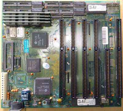
I got this board for the sole purpose of repairing it or at least try doing so.
Mainly I'm reporting back on my progress, and ask for some feedback when something isn't straightforward (mostly a "how to proceed").

It's going to take some time as it is a slow project.

Edit: repaired and working.
https://youtu.be/G2uS0BaOtpM

A big thank you to The Retro Web, source of a lot of stuff of invaluable help.

So far:

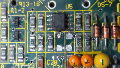
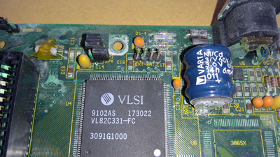
1) removed the battery and neutralized;
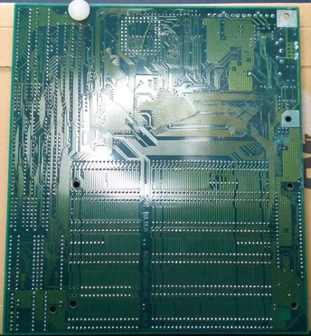
2) cleaned the board twice;
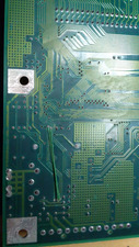
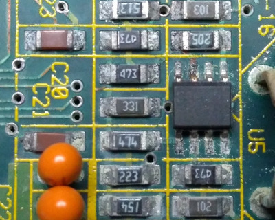
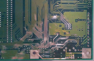
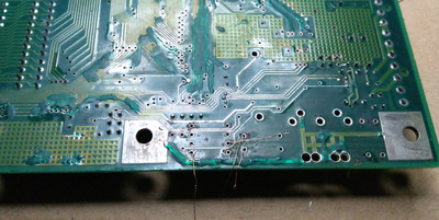
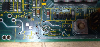
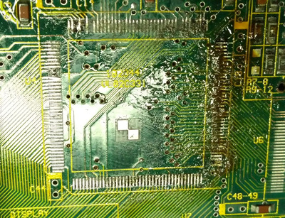
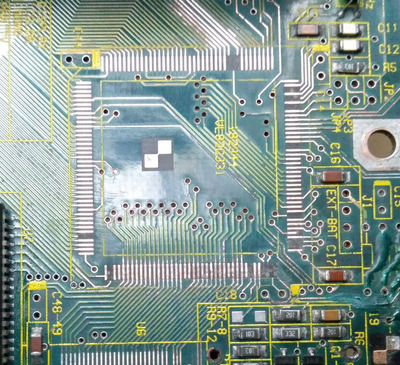
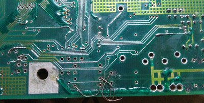
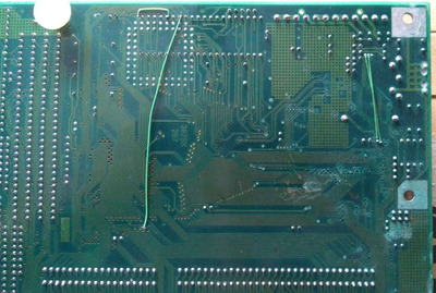
3) polished corroded traces and rebuilt;
4) some solder mask applied;
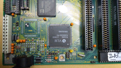
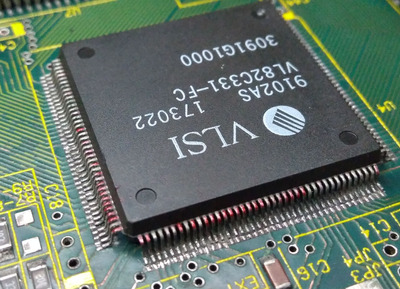
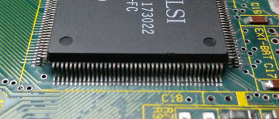
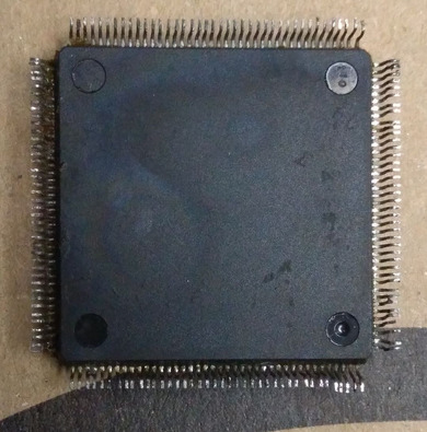
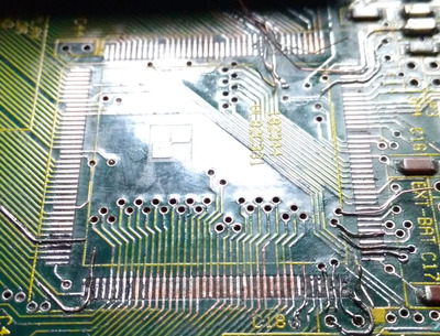
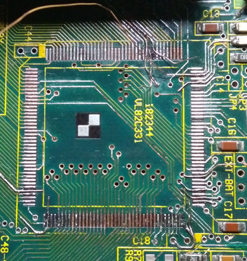
5) chipset desoldered + cleaning and polish

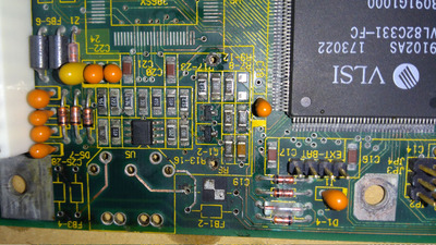
- desolder all that is in the way for trace polishing: caps, keyb connector, jumper pins...
- polish, clean traces
- a ton of continuity tests 😀
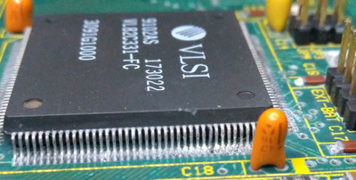
- desolder or try to reflow chipset pins: as much as 30 + a few are soldered to pads that have the trace under the chip itself: I fear ripping it as that would be hard to repair.
- polish legs of chipset
- rebuild broken pads + traces

- anchor wires & traces & pads
-resoldered all the components replacements (new)

To do (in progress):

xx

Attachments

  • 3.jpg
    Filename
    3.jpg
    File size
    343.14 KiB
    Views
    1283 views
    File license
    Fair use/fair dealing exception
  • 1.jpg
    Filename
    1.jpg
    File size
    428.06 KiB
    Views
    1283 views
    File license
    Fair use/fair dealing exception
  • 4.jpg
    Filename
    4.jpg
    File size
    296.78 KiB
    Views
    1283 views
    File license
    Fair use/fair dealing exception
  • 5.jpg
    Filename
    5.jpg
    File size
    311.09 KiB
    Views
    1283 views
    File license
    Fair use/fair dealing exception
Last edited by Nexxen on 2023-10-17, 02:21. Edited 12 times in total.

PC#1 Pentium 233 MMX - 98SE
PC#2 PIII-1Ghz - 98SE/W2K

Reply 1 of 53, by Nexxen

User metadata
Rank Oldbie
Rank
Oldbie

After cleaning:

many traces appear gone but it's just the corrosion under the solder mask that "bubbled" up.
I'll have to polish, tin and rebuild a bunch of these.

A few legs of the chipset aren't making contact, I'll probably have to desolder it and repair pads.

In order to have enough room to work on it I can't but remove a lot of components (caps, isa slot) and probably the keyboard chip.

Doubt:

many smd caps and res solder joints are dull, can I just put some fresh solder to make them shiny? Is it necessary? - I don't think so but...

Attachments

  • 6.jpg
    Filename
    6.jpg
    File size
    178.19 KiB
    Views
    1275 views
    File license
    Fair use/fair dealing exception
  • 2.jpg
    Filename
    2.jpg
    File size
    435.34 KiB
    Views
    1275 views
    File license
    Fair use/fair dealing exception

PC#1 Pentium 233 MMX - 98SE
PC#2 PIII-1Ghz - 98SE/W2K

Reply 2 of 53, by Nexxen

User metadata
Rank Oldbie
Rank
Oldbie

Ram:

4 chips were present: 41256 in parity sockets. Ram chips aren't, probably they were removed and parity left behind.
4 SIPP ram sticks, 2x 44256 + 1x 41256; I guess 1MB in total.

https://theretroweb.com/motherboard/manual/30068.pdf

Attachments

  • 7ram.jpg
    Filename
    7ram.jpg
    File size
    247.65 KiB
    Views
    1267 views
    File license
    Fair use/fair dealing exception

PC#1 Pentium 233 MMX - 98SE
PC#2 PIII-1Ghz - 98SE/W2K

Reply 3 of 53, by Nexxen

User metadata
Rank Oldbie
Rank
Oldbie

In order to desolder the chipset I thought using some low temp solder (I have 135 and 180 °C).

Why desolder it?
If pads are broken I need to rebuild them, and or polish traces and tin + solder mask them.

After some thinking I'll start repairing the traces on the back as I have all the room possible.

PC#1 Pentium 233 MMX - 98SE
PC#2 PIII-1Ghz - 98SE/W2K

Reply 4 of 53, by Nexxen

User metadata
Rank Oldbie
Rank
Oldbie

After another round of vinegar and soap,

- the chipset ic needs desoldering and resoldering to clean the legs and restore the pads on the m/b: there is a white patina I can't get rid of in any way, contact cleaner does close to nothing;
- a lot of traces I first thought were busted in fact had the solder mask lifted and thus are still making a connection; only tinning is required;
- solder of the affected area is dull, would it be best to desolder-resolder with fresh solder?

Any comment or opinion is welcome.

Attachments

  • dullsj2.jpg
    Filename
    dullsj2.jpg
    File size
    339.22 KiB
    Views
    1193 views
    File license
    Fair use/fair dealing exception
  • dullsj.jpg
    Filename
    dullsj.jpg
    File size
    487.63 KiB
    Views
    1193 views
    File license
    Fair use/fair dealing exception

PC#1 Pentium 233 MMX - 98SE
PC#2 PIII-1Ghz - 98SE/W2K

Reply 5 of 53, by rasz_pl

User metadata
Rank l33t
Rank
l33t

I was expecting U5 legs breaking off after cleaning, so thats good I guess 😉 Vias look really thick and strong. Is the PCB 4 layer?

Open Source AT&T Globalyst/NCR/FIC 486-GAC-2 proprietary Cache Module reproduction

Reply 6 of 53, by Nexxen

User metadata
Rank Oldbie
Rank
Oldbie
rasz_pl wrote on 2023-09-07, 18:47:

I was expecting U5 legs breaking off after cleaning, so thats good I guess 😉

I was already planning to dremel the chip's broken pins and solder thin wires to pads.
And I was expecting pads to go bye bye to another dimension.
Yes, it looked awful but in the end it was just that. Even if some solder joints are simply dead from corrosion.

U4 wasn't that much better either... Got lucky I guess.

rasz_pl wrote on 2023-09-07, 18:47:

Vias look really thick and strong. Is the PCB 4 layer?

PCB is 2mm thick, counted 8 dotted lines between the surfaces (if you look directly). Probably 4 layers; no, I can't count layers 🙁

PC#1 Pentium 233 MMX - 98SE
PC#2 PIII-1Ghz - 98SE/W2K

Reply 7 of 53, by Nexxen

User metadata
Rank Oldbie
Rank
Oldbie

U5 is a LM358

I used a fiber glass pen to remove all the corroded patches and traces.
It took forever.
My dremel is dead, I absolutely need to buy a new one. I now understand why it is a must.

I tinned all the exposed traces and I'll cover them with solder mask.

---

I started to remove some through hole components but corroded solder ain't too easy though.
Plain boring.

After examining the chipset legs I discovered that a few are soldered to a loose pad on the motherboard, this makes it more difficult as I have to avoid ripping the pads .
Anchoring them isn't impossible but time is really flying by doing all this work.

---

All the smds that were affected by the leakage must be desoldered and resoldered as they come off pretty easy.
I don't have spares for all values, thus I'll clean the ones I don't have in stock. Not that I have the stock of a pro shop either 😀

Attachments

  • b.jpg
    Filename
    b.jpg
    File size
    418.76 KiB
    Views
    1137 views
    File license
    Fair use/fair dealing exception
  • etchedback.jpg
    Filename
    etchedback.jpg
    File size
    333.39 KiB
    Views
    1138 views
    File license
    Fair use/fair dealing exception
Last edited by Nexxen on 2023-10-17, 02:23. Edited 1 time in total.

PC#1 Pentium 233 MMX - 98SE
PC#2 PIII-1Ghz - 98SE/W2K

Reply 8 of 53, by Nexxen

User metadata
Rank Oldbie
Rank
Oldbie

more work

Attachments

  • 3.jpg
    Filename
    3.jpg
    File size
    382.51 KiB
    Views
    1121 views
    File license
    Fair use/fair dealing exception
  • 2.jpg
    Filename
    2.jpg
    File size
    353.4 KiB
    Views
    1121 views
    File license
    Fair use/fair dealing exception
  • 1.jpg
    Filename
    1.jpg
    File size
    413.01 KiB
    Views
    1121 views
    File license
    Fair use/fair dealing exception

PC#1 Pentium 233 MMX - 98SE
PC#2 PIII-1Ghz - 98SE/W2K

Reply 9 of 53, by Nexxen

User metadata
Rank Oldbie
Rank
Oldbie

more yet

After all the traces I'll try reflowing all the legs.
If it doesn't work I'll then desolder it and check what's under it.

I scraped the legs and the pads and are now shining.
Hope it just works 😀

Any advice is welcome!!!

Attachments

  • 1.jpg
    Filename
    1.jpg
    File size
    633.16 KiB
    Views
    1103 views
    File comment
    red pins are those detached
    File license
    Fair use/fair dealing exception
  • 2.jpg
    Filename
    2.jpg
    File size
    387.2 KiB
    Views
    1108 views
    File license
    Fair use/fair dealing exception
  • 1.jpg
    Filename
    1.jpg
    File size
    336.87 KiB
    Views
    1108 views
    File license
    Fair use/fair dealing exception

PC#1 Pentium 233 MMX - 98SE
PC#2 PIII-1Ghz - 98SE/W2K

Reply 10 of 53, by Nexxen

User metadata
Rank Oldbie
Rank
Oldbie

I have to find a way to make the corrosion patina on the legs and pads to be removed.

As a first idea I can only see mechanic action, or some acid. But what?

PC#1 Pentium 233 MMX - 98SE
PC#2 PIII-1Ghz - 98SE/W2K

Reply 12 of 53, by Nexxen

User metadata
Rank Oldbie
Rank
Oldbie
rasz_pl wrote on 2023-09-09, 20:39:

in theory flux should help remove oxidation

I tried 3 different brands, nothing.
I used my fiber glass pen and it did somehting but I got a full cm off.
We'll see later.

PC#1 Pentium 233 MMX - 98SE
PC#2 PIII-1Ghz - 98SE/W2K

Reply 14 of 53, by Nexxen

User metadata
Rank Oldbie
Rank
Oldbie

New stuff.

Desoldered the chipset IC.

Pin 105 looks not connected, but datasheet has a function for it:
https://4donline.ihs.com/images/VipMasterIC/I … EF6B88F2AEB20B8

Does anyone know what's it for? Is it correct to be not connected?

Attachments

  • pins 104 105.png
    Filename
    pins 104 105.png
    File size
    61.24 KiB
    Views
    888 views
    File license
    Fair use/fair dealing exception
  • a1.jpg
    Filename
    a1.jpg
    File size
    434.24 KiB
    Views
    988 views
    File license
    Fair use/fair dealing exception
  • a2.jpg
    Filename
    a2.jpg
    File size
    205.94 KiB
    Views
    988 views
    File license
    Fair use/fair dealing exception
  • a3.jpg
    Filename
    a3.jpg
    File size
    321.54 KiB
    Views
    988 views
    File license
    Fair use/fair dealing exception
Last edited by Nexxen on 2023-09-14, 14:40. Edited 1 time in total.

PC#1 Pentium 233 MMX - 98SE
PC#2 PIII-1Ghz - 98SE/W2K

Reply 16 of 53, by Nexxen

User metadata
Rank Oldbie
Rank
Oldbie
ChrisXF wrote on 2023-09-13, 01:47:

I've had luck removing pin oxidization with Silvo (liquid silver polish) and in some odd cases Brasso (same deal but made for brass).

Might be worth a go?

This is an idea. Ok, pads on m/b was easy, fiberglass pen and it was fast.
The chipset actually has a sh*tload of oxide on the legs, the fiberglass works to an extent.

I'll look for something in that range and update.
Thanks!

PC#1 Pentium 233 MMX - 98SE
PC#2 PIII-1Ghz - 98SE/W2K

Reply 18 of 53, by Nexxen

User metadata
Rank Oldbie
Rank
Oldbie
rasz_pl wrote on 2023-09-13, 02:15:

or for the price of chemicals you could buy brand new [1pcs] VL82C331-FC Bus Controller QFP160 US $8.15 from Poland.

Too easy. Won't fit. 🤣
My point is to learn from this.

And I already have the stuff, no expenses.

PC#1 Pentium 233 MMX - 98SE
PC#2 PIII-1Ghz - 98SE/W2K

Reply 19 of 53, by Nexxen

User metadata
Rank Oldbie
Rank
Oldbie

I rebuilt traces/pads.
Now I need to anchor them. Some with solder mask others probably epoxy. IDK

Attachments

  • aa3.jpg
    Filename
    aa3.jpg
    File size
    385.88 KiB
    Views
    912 views
    File license
    Fair use/fair dealing exception
  • aa2.jpg
    Filename
    aa2.jpg
    File size
    332.25 KiB
    Views
    912 views
    File license
    Fair use/fair dealing exception
  • aa1.jpg
    Filename
    aa1.jpg
    File size
    302.48 KiB
    Views
    912 views
    File license
    Fair use/fair dealing exception

PC#1 Pentium 233 MMX - 98SE
PC#2 PIII-1Ghz - 98SE/W2K