VOGONS


First post, by Mamba

User metadata
Rank Oldbie
Rank
Oldbie

Hello,
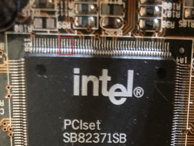
Since I am too stupid to give up I am trying to figure out how to make the onboard usb to work with my GA-586DX
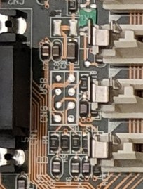
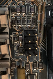
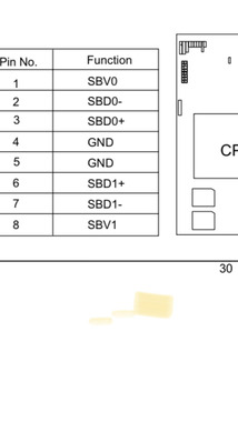
There is a 8pin port for usb, documented.
Jan S helped in sending me a modified bios that allows the usb to be initialised and to have an assigned IRQ.
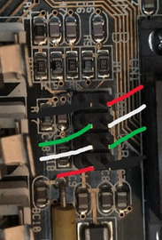
But it does not work, with any combinations of pinouts I a aware of.
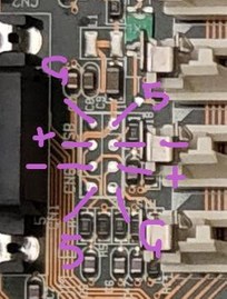
Attached the pinout of the ga-586tx3.
Can someone please take a look and confirm the colore of the cables for this pinout?
Any more ideas?

Thanks

Attachments

  • IMG_5254.jpeg
    Filename
    IMG_5254.jpeg
    File size
    11.86 KiB
    Views
    692 views
    File license
    Fair use/fair dealing exception
Last edited by Mamba on 2023-09-10, 13:57. Edited 1 time in total.

Reply 1 of 17, by majestyk

User metadata
Rank Oldbie
Rank
Oldbie

First make sure the revision of the southbridge (SB82371SB) supports USB. It´s the characters above the "INTEL Ⓜ ©" line, right of the large "i" logo.

Then you need to do sme measuring:
1. Which of the pins of the USB headers are "ground"?
2. Which of the pins of the USB headers are "+5V"?
3. Are the pins 142, 143,144 and 145 connested to pins of the USB headers and to which ones?

Reply 2 of 17, by Nexxen

User metadata
Rank Oldbie
Rank
Oldbie

https://theretroweb.com/motherboards/s/gigabyte-ga-586dx

In the two higher resolution pictures you can see the bare traces.
I don't know if you have headers on yours or if you soldered them.

You can get a Ground reading easily but, if I'm not mistaken, there is a L1 close to the headers connecting to probably +5V? Check if there you have a +5V where a component isn't soldered.
See picture.

Also, order of the two USB ports look inverted:

A B
+5V Gnd
Data + Data -
Data- Data+
Gnd +5V

SBV0 and 1 are +5V in your picture. The others Data + and -.

I could be totally wrong, check thoroughly.

Attachments

PC#1 Pentium 233 MMX - 98SE
PC#2 PIII-1Ghz - 98SE/W2K

Reply 3 of 17, by Horun

User metadata
Rank l33t++
Rank
l33t++

yes the pinout on the board look odd compared to most (where +5 for both is on one end and ground the other end), this is where one of those Startech or Shuttle USB backpanels with two separate 4/5pin connectors would come in handy.
I would do as suggested and try to get just one port working first...as for color: red =+5, green D+, white D- and black ground......if they wired it proper

Hate posting a reply and then have to edit it because it made no sense 😁 First computer was an IBM 3270 workstation with CGA monitor. Stuff: https://archive.org/details/@horun

Reply 4 of 17, by Mamba

User metadata
Rank Oldbie
Rank
Oldbie

Thank you for the replies!
Actually I am not sure about the pinout suggested and orientation at all, sorry!
How can you tell they are inverted? I do not see numbers on the board.
I tried both orientation with no luck,
maybe the order of pinout is not standard also?
Or maybe the usb implementation is so old that nothing works there anyway?

Of course the pin are present, I have not soldered anything, but in my past search for help Jan S. shared a bios with unlocked features like USB initialization. Should be here in the forum.
Once I am back home I will share pictures of the port and verify the southbridge.

Reply 5 of 17, by Nexxen

User metadata
Rank Oldbie
Rank
Oldbie
Mamba wrote on 2023-09-10, 12:45:
Thank you for the replies! Actually I am not sure about the pinout suggested and orientation at all, sorry! How can you tell the […]
Show full quote

Thank you for the replies!
Actually I am not sure about the pinout suggested and orientation at all, sorry!
How can you tell they are inverted? I do not see numbers on the board.
Of course the pin are present, I have not soldered anything, but in my past search for help Jan S. shared a bios with unlocked features like USB initialization. Should be here in the forum.
Once I am back home I will share pictures of the port and verify the southbridge.

1st: use a multimeter to determine where is Ground, to be sure 100%.

In the picture:
on the top right corner you can see a "1" (I didn't notice until now... ); the trace that goes to it is huge and thus probably +5V, it then goes down (bottom left), from there you can deduct that after +5V you have data - (sbd-) follow by data +.

Attachments

  • drawing.jpg
    Filename
    drawing.jpg
    File size
    21.28 KiB
    Views
    595 views
    File license
    Fair use/fair dealing exception

PC#1 Pentium 233 MMX - 98SE
PC#2 PIII-1Ghz - 98SE/W2K

Reply 6 of 17, by Mamba

User metadata
Rank Oldbie
Rank
Oldbie

So here attached the USB area.
How can I test the pin with voltmeter?

And here the southbridge.

Attachments

  • IMG_5256.jpeg
    Filename
    IMG_5256.jpeg
    File size
    525.91 KiB
    Views
    569 views
    File license
    Fair use/fair dealing exception
  • IMG_5257.jpeg
    Filename
    IMG_5257.jpeg
    File size
    96.11 KiB
    Views
    571 views
    File license
    Fair use/fair dealing exception

Reply 7 of 17, by Repo Man11

User metadata
Rank Oldbie
Rank
Oldbie

If you look at this site you'll see two examples of eight pin USB ports. You need to measure the +5 volt pins to determine for sure which yours is - get it wrong and power up with a ground wire connected to the +5... not good. Set your meter to measure DC voltage, and carefully measure the pins, making sure to not accidentally ground the +5 when doing so.

https://web.archive.org/web/20050830011044/ht … le_assembly.htm

"I'd rather be rich than stupid" - Jack Handey

Reply 8 of 17, by majestyk

User metadata
Rank Oldbie
Rank
Oldbie

SU903 supports USB.
Sometimes there are additional components on the mainboard in the signal lines like resistors (about 22R) and capacitors that might be missing when the USB header was not populated.
You can check each of the 4 lines for continuity (Ohmmeter) to make sure all lines are connected to the southbridge correctly.

Reply 9 of 17, by Mamba

User metadata
Rank Oldbie
Rank
Oldbie
majestyk wrote on 2023-09-10, 14:43:

SU903 supports USB.
Sometimes there are additional components on the mainboard in the signal lines like resistors (about 22R) and capacitors that might be missing when the USB header was not populated.
You can check each of the 4 lines for continuity (Ohmmeter) to make sure all lines are connected to the southbridge correctly.

I can check but I am far to be an expert, what setting should I use on the voltmeter and where to put the red and black probes?

Reply 10 of 17, by Repo Man11

User metadata
Rank Oldbie
Rank
Oldbie

Here is a video that covers how to measure DC voltage with a meter. https://twitter.com/JennyChachan/status/1700743568179241293

"I'd rather be rich than stupid" - Jack Handey

Reply 11 of 17, by majestyk

User metadata
Rank Oldbie
Rank
Oldbie

What I meant was if +5v supply and ground are confirmed and the BIOS supports and enables USB and USB still does not work it´s useful to check if the datalines are connected to the south bridge. Therefore you neet to set your multimeter to "resistance" or "ohms" (2K range).
Then you start with pin 142 at the south bridge and mesure the resistance between this pin and each of the 4 data pins of the USB header. At one pin you should measure a resistance of zero 0r 20-47 ohms. Then you rinse and repeat for pin 143, 144 and 145.
Each time there must be a zero (or low) resistance to one of the header pins.
If this is not the case there are probably some missing resistors somewhere in between.

IMG_5256a.jpeg
Filename
IMG_5256a.jpeg
File size
326.48 KiB
Views
483 views
File license
Public domain
Last edited by majestyk on 2023-09-10, 18:47. Edited 1 time in total.

Reply 12 of 17, by Mamba

User metadata
Rank Oldbie
Rank
Oldbie

Unbelievable….
I was able to run XP on the dinosaur with ps/2 ports populated of course, just to see if the usb ports were detected and BAM!!
Yes and no…

They are but with a error mark:

“Your computer's system firmware does not include enough information to properly configure and use this device. To use this device, contact your computer manufacturer to obtain firmware or Bios update. (Code 35)”

From digging on the internet:
This error message is displayed when a device does not have an entry in the BIOS MultiProcessor Specification (MPS) table. You can only see this error message on MPS-capable systems. This behavior usually indicates a BIOS bug. This is particularly prevalent on MPS systems with multiple root PCI buses.

Guess this is why no usb card works here, not even usb of the chipset itself???
How can be possible that no one made a decent bios for this beauty??

Reply 13 of 17, by majestyk

User metadata
Rank Oldbie
Rank
Oldbie

That´s probably the case!
A lot of more modern PCI cards don´t work or don´t work properly on this board.
This BIOS supports SMP and everything, maybe they snatched some tables and data to make it fit.

As long as this issue isn´t sorted you don´t have to bother about the continuity of the data traces of course.

I once had a PCI USB card working on the 586-DX - I think it had an Acer or VIA chip. But then I added a NIC and sound and ended up in IRQ hell as usual.

Reply 14 of 17, by DerBaum

User metadata
Rank Oldbie
Rank
Oldbie

From the manual and the unpopulated header i came up with the same pinout as Nexxen.

IMG_5257.jpeg
Filename
IMG_5257.jpeg
File size
52.24 KiB
Views
461 views
File license
Public domain

FCKGW-RHQQ2

Reply 15 of 17, by Repo Man11

User metadata
Rank Oldbie
Rank
Oldbie

I hope that Jan can help you sort out that BIOS issue. It seems wrong that my super cheap PCChips M520 (VX chipset AT) has working USB and this motherboard doesn't.

"I'd rather be rich than stupid" - Jack Handey

Reply 16 of 17, by Nexxen

User metadata
Rank Oldbie
Rank
Oldbie
DerBaum wrote on 2023-09-10, 18:58:

From the manual and the unpopulated header i came up with the same pinout as Nexxen.
IMG_5257.jpeg

But you made it Italy's flag 😀
Nice touch 😉

PC#1 Pentium 233 MMX - 98SE
PC#2 PIII-1Ghz - 98SE/W2K

Reply 17 of 17, by Mamba

User metadata
Rank Oldbie
Rank
Oldbie
Repo Man11 wrote on 2023-09-10, 19:44:

I hope that Jan can help you sort out that BIOS issue. It seems wrong that my super cheap PCChips M520 (VX chipset AT) has working USB and this motherboard doesn't.

Hope he can…