VOGONS


First post, by tsalat

User metadata
Rank Newbie
Rank
Newbie

Hi guys,

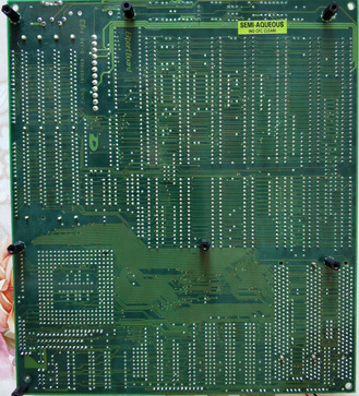
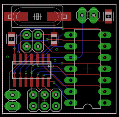
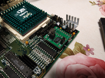
I have got a new board tagged as "not tested" , and I am having problems bringing it to life. The board was in a good condition except for the area around the battery. A few traces were destroyed and the area below was quite oxidated as well.

I have repaired the traces using a silver paint, and verified the continuity. The oxidated areas were cleaned, etc... After setting up the jumpers using the manual here: https://theretroweb.com/motherboards/s/dataex … p4045#downloads I have tried to boot, no beep, and no post even on the debug card.

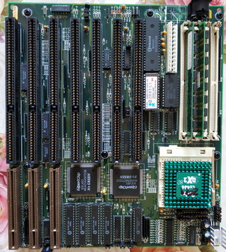
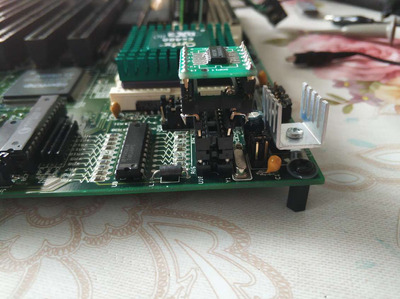
Later on, I have noticed that the linear regulator was missing, next to the cpu on the edge of the board, although I still saw the legs from the former regulator sticking out. The regulator was replaced as well, still no life to the board.

I have also replaced the battery but the battery got from 3,6V to 0,6V in two weeks, no idea from where the drain is coming but measuring the contacts where the battery should be without the battery gives me 4,5V. Still no life.

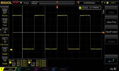
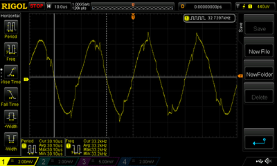
I want to check both crystals during the week but the "barrel" one has no print anymore, and I have no idea what frequency I should expect. Any idea about the value of the crystal?

Also, most if not all of the broken traces were coming to the RTC M5818. Do you think I could replace it with MC146818AP?

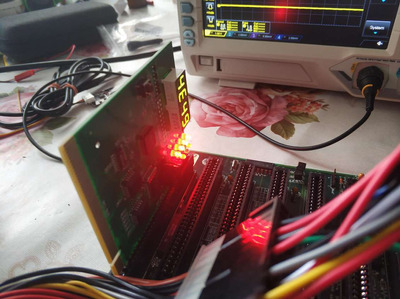
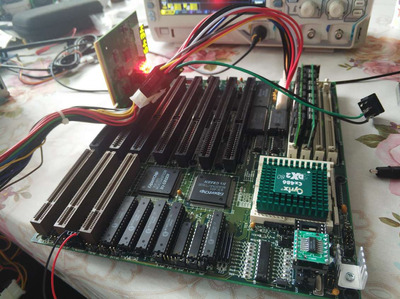
Pictures of the board below:

https://www.sylex.repository.3d-sphere.com/in … iZcZtGmbPyRrzLS
https://www.sylex.repository.3d-sphere.com/in … 3boWFKqXCWdPZTp

any idea what I could try would be appreciated, or measure, or anything 😀

thank you, Tomas

Reply 1 of 14, by piteta

User metadata
Rank Newbie
Rank
Newbie

Hi, according to this thread, that RTC is a clone of the MC part. BTW, I'd say you have a shortcircuit related the battery because in normal conditions it takes more than some weeks to get discharged.

Enough of your games Asthar, this is between you and me.

Reply 2 of 14, by Jester

User metadata
Rank Newbie
Rank
Newbie

I have a similar board that had similar issues. I found out that when 486 boards were being upgraded to Pentium boards, many people pulled the cache chips off. So for me the issue was that the jumpers were configured for 256b of cache that was not on board, and I had to borrow chips off another dead board .

Reply 3 of 14, by tsalat

User metadata
Rank Newbie
Rank
Newbie
piteta wrote on 2023-09-10, 18:00:

Hi, according to this thread, that RTC is a clone of the MC part. BTW, I'd say you have a shortcircuit related the battery because in normal conditions it takes more than some weeks to get discharged.

Hi, thank you for the information about the RTC and the MC, I have ordered the MC already although I am not sure if they will be needed. I agree about the short, the battery life is more than suspicious in this case but I was not able to find the cause for it at this moment.

Jester wrote on 2023-09-10, 18:42:

I have a similar board that had similar issues. I found out that when 486 boards were being upgraded to Pentium boards, many people pulled the cache chips off. So for me the issue was that the jumpers were configured for 256b of cache that was not on board, and I had to borrow chips off another dead board .

I have checked this for a few times and the jumpers seems fine to me, not sure if this would result in a no-go, and no post board, I would assume that at least on the debug card there would be at least some life.

Anyway, I have checked the board today using the oscilloscope, and a few more information and issues 😀.

1) The barrel crystal gives 32,7kHz from one contact (square type) and 32,7kHz from the other contact but with a fussy progress (see the images enclosed)
2) The RTC gives from OSC1, and OSC2 nice square 32,7kHz
3) The crystal next to the CPU, tagged as KTS14,3 - 2,5V input, nothing on the oscilloscope, one or second contact

- I am not sure why the second crystal seems to be dead, is it wort to replace it? Is it 14,3MHz or kHz? EDIT: I guess it is 14,3MHz since I cant find the kHz version.
- During the examination I lost the 3,3V line (diode) on the debug card, the DIODE is not lit right now although it was before. I am sure I did not shorten anything, however, the board was for 15min on before it, I have never tested it for so long. Any idea from where this 3,3V is coming?
EDIT: I have tried a different PSU, and the 3,3V is back.

thank you, Tomas

Attachments

Reply 4 of 14, by piteta

User metadata
Rank Newbie
Rank
Newbie

I don't think it's a problem of wrongly setup cache or cpu. In fact, If the regulator wasn't on the motherboard and you had to install a new one, I'd think that the motherboard is missing more parts, specially around the regulator, or that the regulator you're using is not suitable for this board. Maybe that would explain why there's 2,5V on the 14mhz oscillator. Or maybe it'd confirm there's a short circuit somewhere, but not big enough to blown a fuse. Have you measured the 5V or the current drawn from them?

Enough of your games Asthar, this is between you and me.

Reply 5 of 14, by Nexxen

User metadata
Rank Oldbie
Rank
Oldbie

BIOS chip shows corrosion on legs, remove, clean legs, clean socket, check traces, put back and test.

U15 and 19 don't look good either.

On the back it isn't that good, between the black standoffs I'd check evrything, and clean, scrape, test for continuity...
Close to the bottom a trace coming from the power connector looks eaten away.

Also cpu socket, there's a spot that looks suspicious, check continuity.

Take everything from the beginning and do clean and continuity like it's all you have to do in life 😀 I mean thorough examination.

Attachments

PC#1 Pentium 233 MMX - 98SE
PC#2 PIII-1Ghz - 98SE/W2K

Reply 6 of 14, by tsalat

User metadata
Rank Newbie
Rank
Newbie
piteta wrote on 2023-09-12, 17:26:

I don't think it's a problem of wrongly setup cache or cpu. In fact, If the regulator wasn't on the motherboard and you had to install a new one, I'd think that the motherboard is missing more parts, specially around the regulator, or that the regulator you're using is not suitable for this board. Maybe that would explain why there's 2,5V on the 14mhz oscillator. Or maybe it'd confirm there's a short circuit somewhere, but not big enough to blown a fuse. Have you measured the 5V or the current drawn from them?

The crystal is connected to W83C17 (https://www.datasheets360.com/pdf/5116374762698327081) which if I understand the datasheet right handles the CPU clock, and use the crystal as a reference. I did not see anything else to which it could be connected. The regulator seems to provide 3,3V but at this moment it is turned off since I have switched it to 5V. Nothing is missing around it, I have used a reference picture I have found, and everything is there.

Nexxen wrote on 2023-09-12, 17:50:
BIOS chip shows corrosion on legs, remove, clean legs, clean socket, check traces, put back and test. […]
Show full quote

BIOS chip shows corrosion on legs, remove, clean legs, clean socket, check traces, put back and test.

U15 and 19 don't look good either.

On the back it isn't that good, between the black standoffs I'd check evrything, and clean, scrape, test for continuity...
Close to the bottom a trace coming from the power connector looks eaten away.

Also cpu socket, there's a spot that looks suspicious, check continuity.

Take everything from the beginning and do clean and continuity like it's all you have to do in life 😀 I mean thorough examination.

Yeah, there was lost of corrosion, I have brushed the hell off the board using vinegar, water, and isopropyl alcohol. Next a fiber glass pen but there is still oxidation in this area. When I have time I am removing the oxidation using a sharp blade but it takes forever. I would like to replace most of the smds to make it nice a clean. I have taken out the BIOS a few time to read it out, cleaned the legs, etc... I will do it once more after I will replace the 14,3MHz crystal. I have tested all suspicious traces for continuity, some were painted back, some stayed so far. The traces next to the power pins are having only the upper protective paint damaged but they are working. I will however inspect this once more.

My goal not is to get some signal from the KTS14.3 and the CPU clock by replacing the crystal - Will see if that will help. This will take 2weeks to arrive, heh.
Next is the battery drain, could be a wrong battery, I got them from CN I think, but it could be as well a short. The contacts are however fed good and I could not find a short at this moment.

I will surelly come back to this after I will try that.

best regards, tomas

Reply 7 of 14, by Nexxen

User metadata
Rank Oldbie
Rank
Oldbie
tsalat wrote on 2023-09-12, 18:05:

best regards, tomas

I'd like to remind you that some projects of youtubers took months to solve.
So don't think that if you didn't repair it in 2 days it's impossible.

Stay positive!!

PC#1 Pentium 233 MMX - 98SE
PC#2 PIII-1Ghz - 98SE/W2K

Reply 8 of 14, by tsalat

User metadata
Rank Newbie
Rank
Newbie
Nexxen wrote on 2023-09-12, 18:51:
I'd like to remind you that some projects of youtubers took months to solve. So don't think that if you didn't repair it in 2 da […]
Show full quote
tsalat wrote on 2023-09-12, 18:05:

best regards, tomas

I'd like to remind you that some projects of youtubers took months to solve.
So don't think that if you didn't repair it in 2 days it's impossible.

Stay positive!!

heh, thx, yes, at this moment I am positive, I have some ideas what to try, what to fix, etc... if it will take a week, month or more, I am okay with that. If I will end up in a dead end, I will switch to negative 😁

thx, will keep you updated, tomas

Reply 9 of 14, by piteta

User metadata
Rank Newbie
Rank
Newbie

Hmm... now that you say, if you're using a 5V cpu, the regulator shouldn't be involved, so that shouldn't be the problem... may be while you wait you could disolder the RTC module and check if voltage at the battery goes up from 4.5VDC 5VDC. That would confirm that there's a problem on it.

Enough of your games Asthar, this is between you and me.

Reply 10 of 14, by tsalat

User metadata
Rank Newbie
Rank
Newbie
piteta wrote on 2023-09-17, 07:45:

Hmm... now that you say, if you're using a 5V cpu, the regulator shouldn't be involved, so that shouldn't be the problem... may be while you wait you could disolder the RTC module and check if voltage at the battery goes up from 4.5VDC 5VDC. That would confirm that there's a problem on it.

The RTC module is a DIP socket, and I can try that but I am worry about the W83C17 clock chip. I was fiddling around this a bit more, and the IC should output 14.318 MHz at one pin to the crystal but that pin is dead, no output. The connection to it is simple enough and I cant find anything wrong here. If the W83C17 is bad, I am screwed. I can not find replacement for it. I have found that the MX8315PC is compatible but I can not find this either.

anyone knows a replacement for the W83C17 (even if the pin out is different) that can be still bought from somewhere?

edit: I have found an auction with a damaged board with the same IC, W83C17, wish me luck 😀

thx, tomas

Reply 11 of 14, by tsalat

User metadata
Rank Newbie
Rank
Newbie

Well, the auction went bad, the board I wanted was sold much more expensive that I wanted to spend. However, I have found the MX8315MC on Aliexpress, hopefully it will be the right deal, I need to test it off the board to see if it is working.
I have a two weeks break from this at this moment. Will come back after.

br, tomas

Reply 12 of 14, by tsalat

User metadata
Rank Newbie
Rank
Newbie

Hi Guys,

so, I have got the MX8315MC in the SOP package instead of DIP with some additional SOP to DIP adaptors. Of course, I realized later on that the adaptor is for wide DIP, and I need a narrow one, OMG. Anyway, I have tested the Clock Generator off the board, was working, I have made an "awesome" adaptor to adaptor to fit it in the board, and tested it, but nothing, and no post no beep.

I have checked the rest of the board, the legs on the chipset, etc... nothing, I mean all good. The last attempt was the BIOS, I have read him out, something was there, seemed legit. Luckily the retro web has this board on board with BIOS files. I have compared the same version of it, and to my surprise, the file was slightly different with some HEX positions, usually a few, different from the original one. Programed the one from Retro Web, a voila a post! 😀 I have tested the latest BIOS as well, working, as well with a GPU and DOS, all working.

Now I need to make a custom SOP to DIP to fit it there. I have also noticed that the original clock generator W83C17 has pin 10 on the ground using a 220uf CAP, but the MX8315MC uses a 0,047uf, I need to place this within the custom adaptor. I have added the option to have the reference OSC, and the CAP for pin 10 on this custom board to have the OSC close as possible and bypass the 220uf CAP. I have also tried the UM9515-01 from a non-working board, however, this part was still fed and working on the board and I have checked the pins, the same as the ones above. This IC was not stable there, however, maybe because of the parts around (I can not find a datasheet for this).

so a happy end 😀

tomas

Attachments

Reply 13 of 14, by tsalat

User metadata
Rank Newbie
Rank
Newbie

Hi Guys,

I got the new PCBS for the clock generator and tested yesterday. All working! I have added options to use the crystal from the replacement board or motherboard and to use the capacitor from the motherboard or external.
Happy ending 😀

br, tomas

Attachments

Reply 14 of 14, by tsalat

User metadata
Rank Newbie
Rank
Newbie

Just in case someone would like to replicate this, I have enclosed the Gerber files for the adaptor as well.

BOM:
- OSC: 14,31818 MHz
- C1, C2: 22pF
- C3: 47pF
- IC: MX8315 SOP14

br, Tomas

Attachments