lowlytech wrote on 2023-10-09, 16:13:
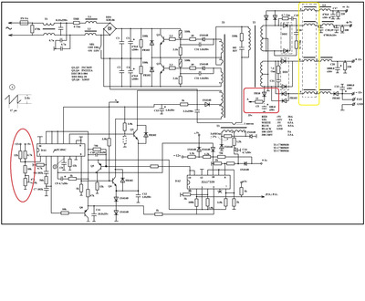
After messing a bit more around with this power supply I think I know now what killed Q1 in the beginning. I didn't realize but the 2625's are not insulated from the heat sinks. Found this out by brushing my hand up against one of the heat sinks when it was on. Gave me a good little buzz. Testing on AC I have about 70-74 volts AC when probing the heat sinks.
If there is no insulating silicon pad and an insulating plastic shim at the screw, the heatsink is "live". Some old IBM supplies even had big warning labels inside calling this out: "ATTENTION: HEAT SINK IS LIVE!". Most AT supplies I have seen use a common heat sink for Q1 and Q2, though, so they have to insulate the heat sink from the transistors. The metal tab of the transistor is at the collector, and the collector is not shared between Q1 and Q2.
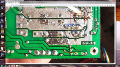
This also explains why you couldn't find any popped component after the "pop" sound: The pop sound was from an arc between the heat sink and the supply case. You might find a spot in the case, though, which looks a bit like a spot welding mark.
lowlytech wrote on 2023-10-09, 16:13:
Checked the power supply while plugged into a motherboard with 1 hard drive connected and off the dim bulb tester. Have 11.6V and 4.9V. Think this looks better.
12V is in spec now, so this is definitely an improvement. 11.6 is still "a bit low". If I am correct with my hypothesis that this supply requires some load on the +5V line, adding extra cards to the ISA bus, like a VGA card, should raise the +12V line even closer to the desired voltage.
As both the 5V and the 12V line are low at the moment, you might also get an improvement by adjusting the output voltage trimmer, if this supply has one. This will raise/lower all voltages of the supply. Before you re-trim the supply, make sure your meter is accurate!. For example, measure the +5V line on a modern ATX supply currently connected to an operating computer (easiest way: plug the probe leads into a 5.25" drive molex power connector), and verify that you get a value quite close to 5V on that 5V line. As 11.6 on the +12V line less than 4% low, I have no better idea for a sufficiently accurate common reference voltage you definitely have at home you can use to check you meter's calibration.