VOGONS


First post, by kingcake

User metadata
Rank Oldbie
Rank
Oldbie

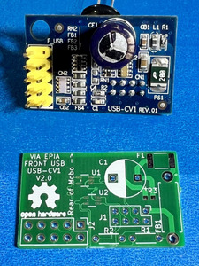
As many of you probably know, several VIA EPIA boards require a special daughterboard (USB-CV1) to make use of the internal USB port(s) header. These are pretty rare to see in the wild. In fact, up until now, I had never even been able to find a picture of one of these things.

I have a saved search on eBay for "EPIA" because I'm a big fan of these boards. Two weeks ago, my eBay app on my phone alerted me to a new listing. Incredibly, the EPIA board listed for sale had one of the mythical USB daughterboards installed on it straight from the factory! I immediately purchased it. The price was high for an EPIA board, but I didn't care. I badly wanted to see one of these up close.

image_67564545.JPG
Filename
image_67564545.JPG
File size
1.63 MiB
Views
1089 views
File comment
VIA USB Daughterboard
File license
CC-BY-4.0

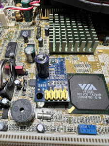
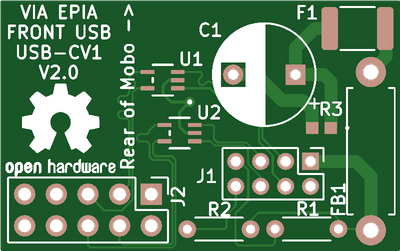
After looking at the board, and the pinouts from the documentation I could find, it appears VIA didn't have room on the motherboard to do bus termination, EMI filtering, and transient voltage protection, or even include a fuse. Hence the need for a daughterboard.

Screenshot 2023-10-13 193135.png
Filename
Screenshot 2023-10-13 193135.png
File size
245.57 KiB
Views
1089 views
File comment
USB Pinouts
File license
CC-BY-4.0

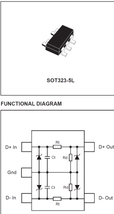
VIA chose discrete parts to do all of this. I'm going with an ST USBDF01W5, a purpose built IC that handles all the passives required for USB 1.1 downstream ports. It does bus termination, EMI filtering, and TVS. They offer two versions with different termination resistances. I chose the one that matches my reverse engineering of VIA's daughterboard. This greatly simplifies the board and BOM.

Screenshot 2023-10-13 195137.png
Filename
Screenshot 2023-10-13 195137.png
File size
42.35 KiB
Views
1089 views
File comment
ST USBDF01W5
File license
CC-BY-4.0

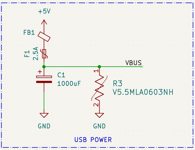
This is my initial schematic for this project:

Screenshot 2023-10-13 192810.png
Filename
Screenshot 2023-10-13 192810.png
File size
94.4 KiB
Views
1089 views
File comment
First Revision
File license
CC-BY-4.0

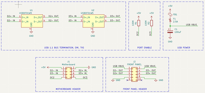
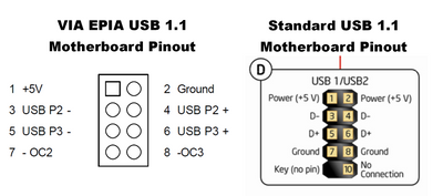
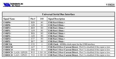
The only thing I'm not sure about is the over current detection pins. AFAIK these are not used for breaking out to standard USB ports, and are only for the mobo to communicate with something like a USB hub IC? The VIA chipset datasheet reads like you just need to pull them high to enable the ports. I'm not sure if the mobo already contains pullups or pulldowns. I will investigate this when I have some more time.

VIA USB.png
Filename
VIA USB.png
File size
344.86 KiB
Views
1089 views
File comment
VIA Datasheet
File license
CC-BY-4.0

Now, I'm no EE. I'm a Computer Scientist by training, but I have been an electronics hobbyist since I was a kid. I would greatly appreciate any input the community might have for me on this project!

I will continue to update this thread with new findings/design revisions as I work on this project.

And yes, I could just use a USB hub to get more than the two ports on the rear of most VIA EPIA motherboards. But I want to use front ports on cases. And this is way more fun!

Also, I will open source and make a Github repo for this once I'm pretty sure the design is appropriate.

Reply 2 of 20, by kingcake

User metadata
Rank Oldbie
Rank
Oldbie
giantclam wrote on 2023-10-14, 02:04:

USB 2.0 and below have a 2.5w (500mA) current limit

VIA's design has one fuse for both ports. I'm assuming they did the combined 1A and then 2.5x to account for inrush. I'm thinking about breaking out the fuses and doing a dedicated fuse for each port.

Reply 3 of 20, by giantclam

User metadata
Rank Member
Rank
Member

Been a long time since I mucked with Eden/EPIA so I don't rightfully recall what they did ~ newer designs can certainly control power on a per port basis ...but overall USB 1.x ( OK for HID devices) is just too slow for me to worry about (ie; I have mainboards with onboard USB 1.x ...never use it, because a USB 2.0 PCI card shames it =) ...ofc, on a EPIA one can't entertain things like this.

Reply 4 of 20, by Horun

User metadata
Rank l33t++
Rank
l33t++

I think the idea to re-create a specific rare board adapter is a great idea ! Hope you can come up with a working solution for those that may want it.
TBH I have never liked micro boards because of the need for such "optional" adapters to fully use what is on the board... just my opinion 😀

Hate posting a reply and then have to edit it because it made no sense 😁 First computer was an IBM 3270 workstation with CGA monitor. Stuff: https://archive.org/details/@horun

Reply 5 of 20, by kingcake

User metadata
Rank Oldbie
Rank
Oldbie
Horun wrote on 2023-10-14, 03:23:

I think the idea to re-create a specific rare board adapter is a great idea ! Hope you can come up with a working solution for those that may want it.
TBH I have never liked micro boards because of the need for such "optional" adapters to fully use what is on the board... just my opinion 😀

Probably nobody wants these but me 🤣. But I'm having fun, and I've been wanting to learn KiCad 😀

Reply 6 of 20, by lti

User metadata
Rank Member
Rank
Member

The overcurrent detection pins are most likely meant for an e-fuse IC (not to be confused with configuration e-fuses inside programmable chips). There are multiple terms for that type of chip ("load switch" seems to be another common one), so I don't know if there's one that I can recommend. It should be in a relatively hobbyist-friendly package for hand soldering (nothing with an exposed bottom pad - those will need hot air or a big hole under the chip for access with a regular iron). VIA took the simple method of using a resettable fuse (polyfuse), but the OC pin on the chipset usually allows the OS to pop up a warning message to tell you why your stuff stopped working.

For protection, the official spec is 500mA, but a little extra for non-compliant devices is nice. A 1.1A resettable fuse per port is the simple method. I don't like having multiple ports share one fuse (as VIA did) because one USB device failing makes multiple devices disconnect at once.

Reply 7 of 20, by kingcake

User metadata
Rank Oldbie
Rank
Oldbie
lti wrote on 2023-10-15, 01:51:

The overcurrent detection pins are most likely meant for an e-fuse IC (not to be confused with configuration e-fuses inside programmable chips). There are multiple terms for that type of chip ("load switch" seems to be another common one), so I don't know if there's one that I can recommend. It should be in a relatively hobbyist-friendly package for hand soldering (nothing with an exposed bottom pad - those will need hot air or a big hole under the chip for access with a regular iron). VIA took the simple method of using a resettable fuse (polyfuse), but the OC pin on the chipset usually allows the OS to pop up a warning message to tell you why your stuff stopped working.

For protection, the official spec is 500mA, but a little extra for non-compliant devices is nice. A 1.1A resettable fuse per port is the simple method. I don't like having multiple ports share one fuse (as VIA did) because one USB device failing makes multiple devices disconnect at once.

Oh nice I didn't know about the e-fuse ICs. I will do research on that!

I found a whitepaper from Littelfuse about USB protection. They claim hot plugging a USB device can result in 3x rated max current draw briefly. So they recommend 1.5A PTC for a 500mA USB 1.1 port. Yes, I agree about a fuse for each port. But I'm running into space constraints trying to do that. Probably why VIA took the easy way out.

In the same whitepaper they also recommend a varistor that clamps at 5.5V across VBUS and Ground. They claim, in testing, that they saw spikes up to 24V while hot plugging devices. So I'm going to incorporate that, as well. Conveniently, they happen to make one for this purpose 🤣.

Reply 8 of 20, by kingcake

User metadata
Rank Oldbie
Rank
Oldbie

Ordered some prototype boards!

This is the initial proof-of-concept board I will make up

beta.png
Filename
beta.png
File size
17.16 KiB
Views
832 views
File license
CC-BY-4.0

I know the layout isn't so hot. But this is just a test board.

I added a 5.5V varistor across VBUS and ground. Several USB design docs I read suggested this as voltages can spike to 24V when hotplugging devices. I kept the 2.5A fuse. Again, design docs recommend this value for two USB 1.1 ports due to inrush currents when hotplugging.

If this concept seems to work, the final design will have dedicated protection for each port independently.

USB Power.png
Filename
USB Power.png
File size
36.32 KiB
Views
832 views
File license
CC-BY-4.0

I've already ordered the parts and solder paste. The PCBs will come with a stencil. I plan to use my hot air station and microscope to make these. Those 0603 parts are tiny!

Reply 10 of 20, by kingcake

User metadata
Rank Oldbie
Rank
Oldbie
giantclam wrote on 2023-10-20, 00:00:

That's pretty cool. Unfortunately that is not the correct board. That's for EPIA boards that use a standard 2.54 header, already have the bus termination, transient voltage suppression, and EMI filtering, on the motherboard.

As you can see from my pics in the first post, the USB-CV1 is way more complicated.

Reply 11 of 20, by lti

User metadata
Rank Member
Rank
Member

I thought the problem with voltage spikes would be on the device end, not the motherboard end.

I wonder why VIA had a 1000uF cap on the 5V supply. I thought they were only supposed to have something like 22uF per port. They might be trying to have the cap supply the initial current when hot-plugging.

Now you're making me reconsider using 750mA fuses per port on a USB card. I never even tested it because I just have socket 7 motherboards and a single PCI slot running through a bridge on my modern computer.

Reply 12 of 20, by kingcake

User metadata
Rank Oldbie
Rank
Oldbie
lti wrote on 2023-10-21, 23:49:

I thought the problem with voltage spikes would be on the device end, not the motherboard end.

I wonder why VIA had a 1000uF cap on the 5V supply. I thought they were only supposed to have something like 22uF per port. They might be trying to have the cap supply the initial current when hot-plugging.

Now you're making me reconsider using 750mA fuses per port on a USB card. I never even tested it because I just have socket 7 motherboards and a single PCI slot running through a bridge on my modern computer.

My guess is they want a lot of local capacitance because it probably doesn't have a very low impedance path through the daughterboard, down the small pins, and then through the motherboard back to +5V.

Reply 13 of 20, by Horun

User metadata
Rank l33t++
Rank
l33t++

The "resettable fuse" idea is good. Make sure you get one that is no more than about 6 volts because even though they are "amp" rated that is at stated voltage. In other words they blow at a certain "wattage",
not really exact but a 250v 1.5 amp will not protect 5v equipment at 1.5amps very well... just a thought

Hate posting a reply and then have to edit it because it made no sense 😁 First computer was an IBM 3270 workstation with CGA monitor. Stuff: https://archive.org/details/@horun

Reply 14 of 20, by kingcake

User metadata
Rank Oldbie
Rank
Oldbie
Horun wrote on 2023-10-22, 03:31:

The "resettable fuse" idea is good. Make sure you get one that is no more than about 6 volts because even though they are "amp" rated that is at stated voltage. In other words they blow at a certain "wattage",
not really exact but a 250v 1.5 amp will not protect 5v equipment at 1.5amps very well... just a thought

Good to know! I just checked and the ones I got from Mouser are 6V.

Reply 15 of 20, by debs3759

User metadata
Rank Oldbie
Rank
Oldbie
kingcake wrote on 2023-10-14, 03:31:
Horun wrote on 2023-10-14, 03:23:

I think the idea to re-create a specific rare board adapter is a great idea ! Hope you can come up with a working solution for those that may want it.
TBH I have never liked micro boards because of the need for such "optional" adapters to fully use what is on the board... just my opinion 😀

Probably nobody wants these but me 🤣. But I'm having fun, and I've been wanting to learn KiCad 😀

I'd be interested for when I get round to testing my EPIA boards. Didn't know a daughter board was needed to enable USB, and I'd like to be able to use USB keyboard and mouse. My biggest problem with these sorts of thread is that I no longer have the eyesight or steady hands to build them, and it's rare that somebody would want to build them to sell.

See my graphics card database at www.gpuzoo.com
Constantly being worked on. Feel free to message me with any corrections or details of cards you would like me to research and add.

Reply 16 of 20, by kingcake

User metadata
Rank Oldbie
Rank
Oldbie
debs3759 wrote on 2023-10-22, 19:48:
kingcake wrote on 2023-10-14, 03:31:
Horun wrote on 2023-10-14, 03:23:

I think the idea to re-create a specific rare board adapter is a great idea ! Hope you can come up with a working solution for those that may want it.
TBH I have never liked micro boards because of the need for such "optional" adapters to fully use what is on the board... just my opinion 😀

Probably nobody wants these but me 🤣. But I'm having fun, and I've been wanting to learn KiCad 😀

I'd be interested for when I get round to testing my EPIA boards. Didn't know a daughter board was needed to enable USB, and I'd like to be able to use USB keyboard and mouse. My biggest problem with these sorts of thread is that I no longer have the eyesight or steady hands to build them, and it's rare that somebody would want to build them to sell.

Your EPIA boards might have the standard USB header. Some do, some don't.

I'll be building these up in the next week or two. If they seem to work ok, I'll gladly send you a prototype to test with. The broader the testing the better.

Reply 17 of 20, by debs3759

User metadata
Rank Oldbie
Rank
Oldbie
kingcake wrote on 2023-10-22, 20:22:
debs3759 wrote on 2023-10-22, 19:48:
kingcake wrote on 2023-10-14, 03:31:

Probably nobody wants these but me 🤣. But I'm having fun, and I've been wanting to learn KiCad 😀

I'd be interested for when I get round to testing my EPIA boards. Didn't know a daughter board was needed to enable USB, and I'd like to be able to use USB keyboard and mouse. My biggest problem with these sorts of thread is that I no longer have the eyesight or steady hands to build them, and it's rare that somebody would want to build them to sell.

Your EPIA boards might have the standard USB header. Some do, some don't.

I'll be building these up in the next week or two. If they seem to work ok, I'll gladly send you a prototype to test with. The broader the testing the better.

I have at least 7 (that's how many I've boxed up and labelled as Epia boards) different boards, so good chance at least one will need it. I'll happily help with testing, thanks.

See my graphics card database at www.gpuzoo.com
Constantly being worked on. Feel free to message me with any corrections or details of cards you would like me to research and add.

Reply 18 of 20, by kingcake

User metadata
Rank Oldbie
Rank
Oldbie
debs3759 wrote on 2023-10-22, 20:37:
kingcake wrote on 2023-10-22, 20:22:
debs3759 wrote on 2023-10-22, 19:48:

I'd be interested for when I get round to testing my EPIA boards. Didn't know a daughter board was needed to enable USB, and I'd like to be able to use USB keyboard and mouse. My biggest problem with these sorts of thread is that I no longer have the eyesight or steady hands to build them, and it's rare that somebody would want to build them to sell.

Your EPIA boards might have the standard USB header. Some do, some don't.

I'll be building these up in the next week or two. If they seem to work ok, I'll gladly send you a prototype to test with. The broader the testing the better.

I have at least 7 (that's how many I've boxed up and labelled as Epia boards) different boards, so good chance at least one will need it. I'll happily help with testing, thanks.

A fellow EPIA hoarder! 🤣

Reply 19 of 20, by kingcake

User metadata
Rank Oldbie
Rank
Oldbie

Got the boards today! Holy crap, look how tiny the pads are for U1 and U2! I will definitely have to make these under a microscope...

Don't know if I mentioned it, but these tiny boards are actually 4-layer. Middle layers are VBUS and GND to reduce EMI.

image_50726401.JPG
Filename
image_50726401.JPG
File size
328.65 KiB
Views
581 views
File license
CC-BY-4.0
image_50769153.JPG
Filename
image_50769153.JPG
File size
289.96 KiB
Views
581 views
File license
CC-BY-4.0