VOGONS


Help identifying this motherboard

Topic actions

Reply 20 of 30, by majestyk

User metadata
Rank Oldbie
Rank
Oldbie

Looking at the tiny heatsinks I don´t believe they will provide more power.

When selecting a PSU (in case you don´t have the original one) have an eye on the 5V rail!
The CPUs alone will draw up to 30A. Plus chipset, harddrives and stuff.

Reply 22 of 30, by andrean

User metadata
Rank Newbie
Rank
Newbie
luckybob wrote on 2023-10-20, 17:29:

hoo boy, thats a loaded question.

it uses standard voltages. nothing special. it conforms mostly to the ATX specifications, afaik. But it is a 100% proprietary power supply.

I've heard of people that cobbled together a DIY solution. You aren't going to need anything overly special, however it is going to require a strong 5v supply. I'll have to pull my own ALR system apart to get a pinout. I dont have any spare power supplies, but I might have a spare power supply CAGE, and that would be a starting place to make a DIY solution. i'll see if I can get to my system this weekend.

is this the power supply that I would need (by any chance)?

https://www.ebay.com/itm/141540346173

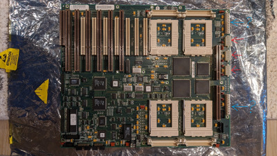
I can see it has 3 connectors that are present on the board as well (marked with red on the attached pic), but I am not sure what are these other two connectors are (is this supposed to be also for the power supply or something else - marked with blue on the pic)?

Attachments

Reply 23 of 30, by luckybob

User metadata
Rank l33t
Rank
l33t

right brand. but thats the standard big-box AT power supply.

the 3 extra connectors are 5v.

I got the machine out of storage, i'll take some pics as soon as I can.

It is a mistake to think you can solve any major problems just with potatoes.
Reply 24 of 30, by andrean

User metadata
Rank Newbie
Rank
Newbie
luckybob wrote on 2023-10-25, 01:15:

right brand. but thats the standard big-box AT power supply.

the 3 extra connectors are 5v.

I got the machine out of storage, i'll take some pics as soon as I can.

Thanks, much appreciated!

Reply 25 of 30, by luckybob

User metadata
Rank l33t
Rank
l33t

https://imgur.com/a/fyX1HIx

I got out my spare power supply chassis. it is the same box as the full 6x6 and the quad that you have.

There are 10-pin 5v power for the cpu cards - but those arent used in your case. 5 of the wires are ground, 5 are +5v. all these cables are wired the same

the grey connection is for 3.3v power to the PCI slots.

The small connections are basically the extra wires that ATX uses to power everything up. But you should be able to just force power the board.

It is a mistake to think you can solve any major problems just with potatoes.
Reply 26 of 30, by andrean

User metadata
Rank Newbie
Rank
Newbie
luckybob wrote on 2023-10-30, 03:25:
https://imgur.com/a/fyX1HIx […]
Show full quote

https://imgur.com/a/fyX1HIx

I got out my spare power supply chassis. it is the same box as the full 6x6 and the quad that you have.

There are 10-pin 5v power for the cpu cards - but those arent used in your case. 5 of the wires are ground, 5 are +5v. all these cables are wired the same

the grey connection is for 3.3v power to the PCI slots.

The small connections are basically the extra wires that ATX uses to power everything up. But you should be able to just force power the board.

wow, ok, thanks a lot for getting all the photos! Sadly there are no such models listed on ebay currently. I have a couple questions:

1. P8 and P9, what are they used for?
2. My board has only three connectors that look like P13, P14, P15, P1, P5, P7 , is that because your board has 6 such connectors and you used them all, whereas I could pick from those any three and use them?
3. I also see no connector for P3 on my board, is that correct?
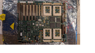
4. I'm not sure what are the two connectors I marked on my board in the attached photo?

Thanks!

Attachments

Reply 27 of 30, by luckybob

User metadata
Rank l33t
Rank
l33t

1- 8 and 9 are the standard AT power connections to the mainboard
2- the bigger board, the 6x6. has the processors moved off the motherboard and onto cpu cards. they are the same size as the memory board you have.
3- the 12-pin connection should be there... its the only source of 3.3v for the pci bus... it looks like your board does not have this connection populated, so your pci slots are likely 5v only.
4- i dont see that image? but someone else pointed out the damage to the brown pci slot. this is critical to be repaired. there is a special card that fits in that sloth that allows you to connect the keyboard/mouse

edit: i see the attachment now. a common way to increase power is to connect a 2nd power supply. it looks like this is the case here

It is a mistake to think you can solve any major problems just with potatoes.

Reply 28 of 30, by andrean

User metadata
Rank Newbie
Rank
Newbie
luckybob wrote on 2023-11-01, 16:18:

1- 8 and 9 are the standard AT power connections to the mainboard

Thanks, my board doesn't seem to have these, is that possible?

luckybob wrote on 2023-11-01, 16:18:

4- i dont see that image? but someone else pointed out the damage to the brown pci slot. this is critical to be repaired. there is a special card that fits in that sloth that allows you to connect the keyboard/mouse

thanks, yes, that will be repaired before I do anything with the board. I am not sure where I will find the I/O module that goes into that broken slot, but I will keep looking.

Reply 29 of 30, by luckybob

User metadata
Rank l33t
Rank
l33t

you have 2 sets? they are the connections you have circled in the attached image.

For testing, I would get a AT power supply, with a BEEFY 5v rail. you can connect to the top circled connection. That should be enough for a basic smoke-test. With a volt meter, you can then see what pins are 5v and jerry-rig an adapter to supply some extra amperage to those pins.

keep it to one cpu and minimal ram. (it requires groups of FOUR, and start from the bottom slots going up). just go for a smoke test. I do have a pic of the mouse/kb card and will attach it below.

https://imgur.com/a/TpBNQB7

It is a mistake to think you can solve any major problems just with potatoes.

Reply 30 of 30, by luckybob

User metadata
Rank l33t
Rank
l33t

GOOD NEWS!!!

I walked by the rack chassis this board fits into.

I thought I had a motherboard in it, but it became aparent I did not.

The 6x6 power supply is *mostly* the same, but I did take a couple important images: https://imgur.com/a/ZIzfRYH

#1 gives you jumper info
#2 shows the different power connections than what I had posted. So it does NOT take a pair of AT power supplies. it does use the 2nd connection as a 3.3v input.

As for which one is which.... the connectors are keyed, so I got my motherboard out and.... i'm super glad I did because they pulled a sneaky on the 3.3v connection. its backwards to the normal AT connection. Also the AT connection looks like it is at the TOP (of your image) with the 3.3 at the bottom.

the 10-pin connections are the same, and are all 5v.

I know they make ATX to AT adapters that ALSO split out the 3.3v they are NOT common. https://www.bicker.de/en/x1-116_atx_at_adapte … nboards?nbnet=1# This particular adapter is wired to be always on, however...

It is a mistake to think you can solve any major problems just with potatoes.