First post, by tsalat
Hi,
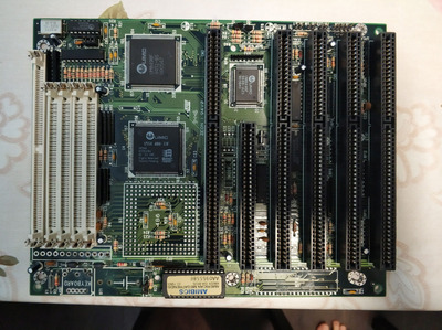
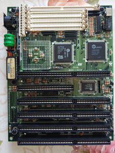
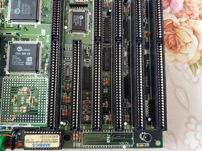
I was recently repairing an old 486 board with embedded CPU damaged by battery leak, and ended up with "Keyboard Error" message. The board is labelled as ZEON 94V0 but I couldn't find any information about it. Visually, the A-Trend ATC-1411A appears to be the exact board (https://theretroweb.com/motherboards/s/a-trend-atc-1411a). The board has no dedicated IC for the keyboard. I have repaired the traces that were broken, the one I have found, and replaced the keyboard connector as well. The board will boot up to the BIOS error message, debug card no error, claiming an issue with the keyboard.
- The keyboard will blink at the beginning.
- The GND, 5V are fine, NC is not connected.
- The DATA in has 5V without the connector plugged, connected to the UMC UM8496F
- The CLK pin has 0V without the connector, and 5V after the keyboard is connected
- The fuse is just a wire, from the production, all good here.
I went through the board a few times, found two issues on the way of looking for the keyboard error but nothing solved the keyboard issue. The keyboard is fine, I have tried another PS2 with the same outcome.
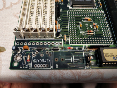
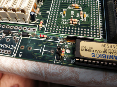
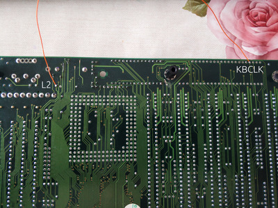
The broken traces next to the battery were not connected to the keyboard plug, the DATA line went above that area and is fine. I have added some pictures about how it was looking before and after.
The CLK trace is going from the back side of the board to an inductor and from there to a capacitor next to the SIMM slots. From this moment I have no idea where it goes, the capacitor seems to be there only as a filter, nothing is going away from him and the other leg is GND, make sense. The trace from the CLK is beneath the SIMM slots and I cant find where it goes further - I have been beeping for an hour with no positive location of the trace behind the location I can see from the back side of the board.
I am not sure now about both the CLK and the DATA of course.
Does the CLK should be 0V without the keyboard plugged in? Does it make sense that after plugging the keyboard the voltage goes to 5V on the CLK pin?
What is generating the CLK for the keyboard connector? This could help me to find the trace I am missing and maybe locate the issue. I do not have an OSC at this moment so can not check if any CLK is reaching the keyboard. Is the clock coming from the clock generator? - the peripheral output? - I would assume that even the ISA slots would be dead in this case but they are getting 2,5V on the OSC pin.
ahhh, I am so lost at this moment and need some advise 😀.
any help and advise would be appreciated, thank you Tomas