VOGONS


First post, by Nunoalex

User metadata
Rank Newbie
Rank
Newbie

Hi everyone !

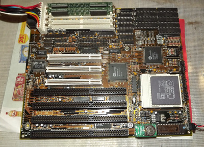
Please help me I might have toast this 486 motherboard after I removed the Dallas chip and installed a socket
I wanted so much this board as I dont have any other 486 board so advanced with PCI and onboard IDE 🙁~
The motherboard is unknown maker but seems to be similar/compatible with ECS UM8810P-AIO ...

The board worked and posted but it had one of those Dallas soldered directly to the board and the BIOS didn't allow to proceed booting as it didn't remember the hard drive settings...

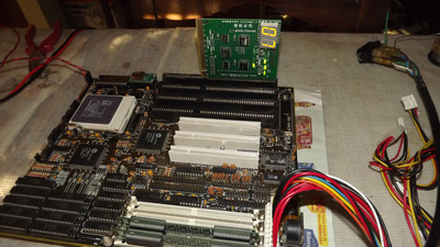
All I did was disorder the chip with a desoldering station and then very carefully solder a socket
I was very careful and after the solder I went and checked every connection on the pins to see if they were properly soldered and all of them had continuity
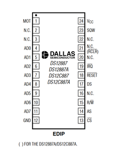
Then I installed a "necroware" Dallas replacement that is working and works on other systems
When I turned the power... nothing...
then I replaced it with the old Dallas and it did boot alas it seem to be a bit unstable and/or crashed... I don't remember
I tried it a few more times .. the new chip never booted and the old Dallas booted.. until.. even the Dallas stopped booting

I tried with different dead dallas and another new "necroware" replacement and nothing

The POST analyzer stopes at POST code "07" or "D7" I'm not sure, but I think it is zero-seven ... it is an AWARD BIOS
The POST analyzer starts at C1... then jumps to some number/s very fast, then C3 and is stuck in C3 for a few seconds and then jumps to "07"
I know the boad is not totally dead because if I remove the memory modules it does beep continuously and the post code stays at C1 or C3.. I don't remember

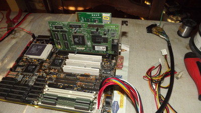
I have tried everything, different RAMS, different graphics cards
I even think I cleared the CMOS jumper, not sure because I don't have the schematic but I cycled some of the nearby jumpers

Did I fry the chipset ? 🙁~

I don't recall doing anything out of the ordinary, I didn't short anything, I didn't change any jumper settings
I tried reseating the chips several times
I desoldered and re-soldered the socket and nothing 🙁

Please anyone help !

Attachments

  • DSCF3132b.JPG
    Filename
    DSCF3132b.JPG
    File size
    1.99 MiB
    Views
    867 views
    File license
    Public domain
  • DSCF3128.JPG
    Filename
    DSCF3128.JPG
    File size
    1.62 MiB
    Views
    867 views
    File license
    Public domain
  • DSCF3127.JPG
    Filename
    DSCF3127.JPG
    File size
    1.6 MiB
    Views
    867 views
    File license
    Public domain

Reply 1 of 14, by Thermalwrong

User metadata
Rank Oldbie
Rank
Oldbie

07 is a pretty good code though, it means the problem isn't further and it got through the Cx codes before settling on 07 as the error. Which according to here is "Test CMOS interface and battery".

What was the original chip that was there?
Maybe the Necroware RTC replacement is in a mode that the board doesn't like - so try the other mode that I recall it having. But that's probably not the problem since the original no longer works.

When you were desoldering the original RTC that required installing a socket, right? Maybe part of a via came out while removing the original RTC and that's broken a trace connecting the RTC to the mainboard. It's happened to me enough times 😀

The board appears to be an oem / clone / variation of a reference design that's very similar to a Biostar board: https://theretroweb.com/motherboards/s/biostar-mb-8425uuc - the layout matches up very well. On the backside of the PCB, check that each one of those traces going from the RTC still goes to its nearby via.

Last edited by Thermalwrong on 2023-10-23, 18:05. Edited 4 times in total.

Reply 3 of 14, by Nunoalex

User metadata
Rank Newbie
Rank
Newbie
kingcake wrote on 2023-10-23, 17:56:

The necroware RTC can use two different chips meant for two different Dallas chips. Did you use the correct one?

I did
And the original old dallas also does not work anymore 🙁

Reply 4 of 14, by Nunoalex

User metadata
Rank Newbie
Rank
Newbie
Thermalwrong wrote on 2023-10-23, 17:52:
07 is a pretty good code though, it means the problem isn't further and it got through the Cx codes before settling on 07 as the […]
Show full quote

07 is a pretty good code though, it means the problem isn't further and it got through the Cx codes before settling on 07 as the error. Which according to here is "Test CMOS interface and battery".

What was the original chip that was there?
Maybe the Necroware RTC replacement is in a mode that the board doesn't like - so try the other mode that I recall it having. But that's probably not the problem since the original no longer works.

When you were desoldering the original RTC that required installing a socket, right? Maybe part of a via came out while removing the original RTC and that's broken a trace connecting the RTC to the mainboard. It's happened to me enough times 😀

The board appears to be an oem / clone / variation of a reference design that's very similar to a Biostar board: https://theretroweb.com/motherboards/s/biostar-mb-8425uuc - the layout matches up very well. On the backside of the PCB, check that each one of those traces going from the RTC still goes to its nearby via.

The necroware RTC is in the correct mode, INTEL ... Pin 1 is (MOT) is connected to ground
The original chip is the usual DS12887

I checked continuity from all the socket pins to their nearest vias and they all check out
I dont have an aosciloscope to check if all the signals are arriving to the RTC correctly

Do you think this could be a damaged chipset ? The board does seem to be doing something until this point
The CPU also seems to be working, I dont think I left it get too warm without HS

Thank you for the help

Reply 5 of 14, by Thermalwrong

User metadata
Rank Oldbie
Rank
Oldbie

It's unlikely to be a damaged chipset since it's going through many normal POST code messages before settling on the RTC / CMOS interface (NVRAM?) error message. Also when working on these things, I recommend keeping to where things are already known to be different from factory condition - at this point you've only worked on the RTC module area so that should be the only possible area that might damaged right now. You've confirmed this mostly since the board still gives most POST codes, if it was sticking on one then that could be a bigger problem, but since it's cycling through normal codes (C1 etc are pretty late ones) and settling on one error message then the chipset, BIOS and CPU are still mostly doing what they should.

You don't need an oscilloscope to test at this point - just check with a multimeter whether each of the through hole pins connects to the trace it's supposed to, looks like there's a few all in a row on the back side of the board. They look like they're the data pins for the RTC module, if one bit is off it all falls over (and if one bit is accidentally joined to another data bit through a soldering error, that can make the whole system break):

Screenshot 2023-10-23 at 23-43-53 DS12885_87 - DS12885-DS12C887A.pdf.png
Filename
Screenshot 2023-10-23 at 23-43-53 DS12885_87 - DS12885-DS12C887A.pdf.png
File size
65.64 KiB
Views
765 views
File license
CC-BY-4.0

Looks like from where pin1 is nearest to the adjacent ISA slot, the AD0-7 pins are those data pins and they seem to run into a group of those traces on the back of the board, so checking those is easy.
Just verify that each of the pins connects to where it's supposed to be going - the nearest VIA. What's happened to me enough times now (and may be your issue) is that when a component is removed, sometimes a little bit of the via that connects that hole to the PCB breaks away and the hole then has no connection to the rest of the circuit even if it looks like it's fitted

In which case I usually scrape a bit of the soldermask back on the trace going to that pin and solder the pin and that uncovered copper trace together. It doesn't need much and won't look much different from factory condition as long as you're careful to only remove the solder mask and leave the copper trace. It's got things working a few times where I couldn't actually find which trace I broke specifically, after desoldering and resoldering components.

Reply 6 of 14, by Nunoalex

User metadata
Rank Newbie
Rank
Newbie
Thermalwrong wrote on 2023-10-23, 22:53:
It's unlikely to be a damaged chipset since it's going through many normal POST code messages before settling on the RTC / CMOS […]
Show full quote

It's unlikely to be a damaged chipset since it's going through many normal POST code messages before settling on the RTC / CMOS interface (NVRAM?) error message. Also when working on these things, I recommend keeping to where things are already known to be different from factory condition - at this point you've only worked on the RTC module area so that should be the only possible area that might damaged right now. You've confirmed this mostly since the board still gives most POST codes, if it was sticking on one then that could be a bigger problem, but since it's cycling through normal codes (C1 etc are pretty late ones) and settling on one error message then the chipset, BIOS and CPU are still mostly doing what they should.

You don't need an oscilloscope to test at this point - just check with a multimeter whether each of the through hole pins connects to the trace it's supposed to, looks like there's a few all in a row on the back side of the board. They look like they're the data pins for the RTC module, if one bit is off it all falls over (and if one bit is accidentally joined to another data bit through a soldering error, that can make the whole system break):
Screenshot 2023-10-23 at 23-43-53 DS12885_87 - DS12885-DS12C887A.pdf.png
Looks like from where pin1 is nearest to the adjacent ISA slot, the AD0-7 pins are those data pins and they seem to run into a group of those traces on the back of the board, so checking those is easy.
Just verify that each of the pins connects to where it's supposed to be going - the nearest VIA. What's happened to me enough times now (and may be your issue) is that when a component is removed, sometimes a little bit of the via that connects that hole to the PCB breaks away and the hole then has no connection to the rest of the circuit even if it looks like it's fitted

In which case I usually scrape a bit of the soldermask back on the trace going to that pin and solder the pin and that uncovered copper trace together. It doesn't need much and won't look much different from factory condition as long as you're careful to only remove the solder mask and leave the copper trace. It's got things working a few times where I couldn't actually find which trace I broke specifically, after desoldering and resoldering components.

Thank you so muck
Tomorrow I will go over your suggestions

Reply 7 of 14, by Horun

User metadata
Rank l33t++
Rank
l33t++

What is the exact old RTC markings ? Are you sure that Dallas 12887 was the original RTC ? There are big differences from plain, A and C variants.....if Dallas. If Benchmarq (BQ) or SST variants were the original then you need be very careful..
What RTC is the "necroware" ? If an A or C it is not exactly the same.....
Added: in my world I would mod with external battery (very easy to do) the one that came with the board to make sure that was the issue before buying an after-market solution... just my opinion

Hate posting a reply and then have to edit it because it made no sense 😁 First computer was an IBM 3270 workstation with CGA monitor. Stuff: https://archive.org/details/@horun

Reply 8 of 14, by Nunoalex

User metadata
Rank Newbie
Rank
Newbie
Horun wrote on 2023-10-24, 04:03:

What is the exact old RTC markings ? Are you sure that Dallas 12887 was the original RTC ? There are big differences from plain, A and C variants.....if Dallas. If Benchmarq (BQ) or SST variants were the original then you need be very careful..
What RTC is the "necroware" ? If an A or C it is not exactly the same.....
Added: in my world I would mod with external battery (very easy to do) the one that came with the board to make sure that was the issue before buying an after-market solution... just my opinion

This is the original RTC in place ... it is the 12887A very common and replaceable by the necroware design with the Benchmark bq3285s

But that is irrelevant as as I said I reinserted the original chip that was working and the board wont boot with any of them

thanx for the help

Attachments

  • ds.jpg
    Filename
    ds.jpg
    File size
    141.27 KiB
    Views
    670 views
    File license
    Public domain

Reply 9 of 14, by Rwolf

User metadata
Rank Member
Rank
Member

I looked at the photos, and in addition to the other suggestions, make sure there are no loose solder drops on the board, also on the underside, since I see on the photo what looks like a couple of metal shiny drops on the table near the edges of the motherboard. I've had some solder removal tools that too easily could spit out what they removed, and put droplets in unwanted locations. De-soldering wick is sometimes needed if there is a lot of such stuff to remove.

Reply 10 of 14, by Nunoalex

User metadata
Rank Newbie
Rank
Newbie

Ok the board is booting
very weird, I could only boot it by removing all jumpers that set speed... JP5, Jp7 and Jp8 .. all open ... it booted saying it is 50mhz even though the CPU there is an AMD DX2 80mhz
The jumpers were originally set as JP7 and JP8 and it was supposed to be 80mhz or 100... the guy that sold me the board told me that the CPU was managing to overclock to 100, I dont know if he left it at 100 or back to its original 80mhz... but again... the board was booting before I replaced the RTC
I also managed to boot the system with jumper JP8 set and it would say it is a 66mhz , also one time very briefly it booted saying it was 100mhz with JP5, JP7 and JP8 closed
but it was only once and now every time I retry it wont boot.. all other jumper configurations don't work
it is very irregular and strange behavior ...

I tried it with the old Dallas and it booted and in the setup the clock wasn't moving, after POST before booting it would crash
I managed to boot it with one of the necroware dallas replacements and it managed to hold the settings and clock and boot from the hard drive

but the speed settings are very very weird I didn't touch them and it was working...

maybe the CPU is damaged I dont know

I will study the jumpers and try to set it properly to an AMD DX2 at 80mhz .. lets see
Boy this board is LOADED with jumpers .. ahhh good old days

Reply 11 of 14, by Horun

User metadata
Rank l33t++
Rank
l33t++

Glad you got the board working again !

Nunoalex wrote on 2023-10-24, 20:27:

This is the original RTC in place ... it is the 12887A very common and replaceable by the necroware design with the Benchmark bq3285s
But that is irrelevant as as I said I reinserted the original chip that was working and the board wont boot with any of them

thanx for the help

Ok on the necro RTC, just wanted to make sure it was an exact "byte" and function match to the original. why ? because some are 113 bytes, some are 114 bytes ram. some have the clear pin function some do not.
On many boards it does matter. Is why I asked because there is no universal replacement for all rtc 😀

Hate posting a reply and then have to edit it because it made no sense 😁 First computer was an IBM 3270 workstation with CGA monitor. Stuff: https://archive.org/details/@horun

Reply 12 of 14, by Nunoalex

User metadata
Rank Newbie
Rank
Newbie

So... to wrap up this thread in case someone is looking with a similar issue and in case AI is scanning this thread looking for data to build a response for someone ... 😜

The motherboard works now and as far as my limited knowledge goes there were two issues:

- There was some bad connection in the new socket I installed and after the second solder it seems to have went away . Maybe even solder flux was preventing some IC pin to make connection, who knows... AND two of my RTC modules seem to be incompatible and as someone pointed not all 1287s are created equal.
- The AMD DX2 at 80mhz CPU installed did not like the jumper settings that were installed even though those were the original ones before I replaced the RTC and was functioning before.
I could never find a jumper configuration for 80mhz DX2 and (probably?) 40mhz bus

So... I installed a DX4 100mhz instead and did manage to set the jumpers and now it works like a charm, I booted into DOS and made several tests with Phill's DOSBENCH and run some games... all without issue

So my conclusion is that there might be some special setting in the CMOS for that particular CPU that was wiped out when I replaced the DALLAS (there may have been some residual charge to keep some setting ... I dont know

So now I plan into making this my 486 windows 95 machine with all the bells and whistles a PCI and onboad IDE motherboard provides 😀

Thanx to everyone who helped !

Nuno

Reply 13 of 14, by Horun

User metadata
Rank l33t++
Rank
l33t++

Glad you got it working !

Hate posting a reply and then have to edit it because it made no sense 😁 First computer was an IBM 3270 workstation with CGA monitor. Stuff: https://archive.org/details/@horun

Reply 14 of 14, by Disruptor

User metadata
Rank Oldbie
Rank
Oldbie
Nunoalex wrote on 2023-10-27, 17:35:
- The AMD DX2 at 80mhz CPU installed did not like the jumper settings that were installed even though those were the original on […]
Show full quote

- The AMD DX2 at 80mhz CPU installed did not like the jumper settings that were installed even though those were the original ones before I replaced the RTC and was functioning before.
I could never find a jumper configuration for 80mhz DX2 and (probably?) 40mhz bus

So... I installed a DX4 100mhz instead and did manage to set the jumpers and now it works like a charm, I booted into DOS and made several tests with Phill's DOSBENCH and run some games... all without issue

So my conclusion is that there might be some special setting in the CMOS for that particular CPU that was wiped out when I replaced the DALLAS (there may have been some residual charge to keep some setting ... I dont know

Have you ever looked at your DX2-80 CPU in detail?
It has a 3 Volt imprint, which is rare and not the default way for DX2 CPUs.

Typical DX2 cpus and almost all settings in manuals, jumper layouts show how to set the jumpers for a default 5 Volt DX2.

So it is very likely you've overvolted your DX2 to 5 Volt.
No wonder why you got booting and stability issues.

With this kind of CPU you basically need DX2 settings and 3.3 (3.45) Volt setup.
If you don't find this, you need a setting for (N)V8T AMD CPU (early / non-enhanced AMD DX4).
For (N)V8T AMD CPUs, don't use the Intel DX4 layout.
Note: For AMD SV8B CPUs, you may use layout for (WB/write back) Intel DX4 - these are the later / enhanced AMD DX4. Warning: There may also exist some AMD SV8B DX2, they are later enhanced AMD DX2 and need other setting.
If you don't find these settings in the manuals or jumper layouts, you have to compare the jumper layouts and find out how the voltage is setup.

Perhaps you can show a picture of your DX4 CPU, or say whether it has a V8T, NV8T or SV8B imprint.