First post, by kinetix
Greetings to the Vogonists
I need some help with a difficult task.
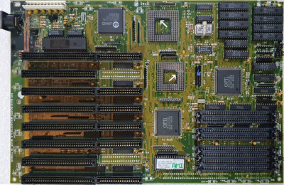
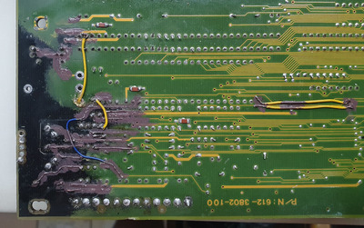
I have "saved" this motherboard from a recycling center (when I go there I have to check a lot and carefully to find something older, since almost everything is more modern, post-2000 hardware). I couldn't find it on TheRetroWeb, so I contributed it, and the guys identified it as an "Ultima Electronics Corp. 3802". It's a 386. I don't have 386 CPUs now (except an SX without legs,), but I do have a TX486DLC/E-40GA, and I understand that it is a drop in upgrade. Even without being sure it is supported, I want to restore the motherboard (the other 386 I have is a small Foxcon M396F, but I don't have CPUs to improve the poor 386SX it has).
But the condition of this motherboard is BAD.
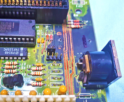
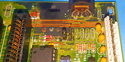
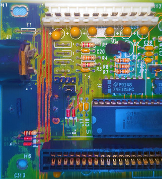
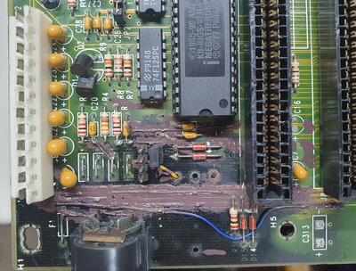
On the one hand, it received a hit that destroyed an array of resistors, but that is easy to repair.
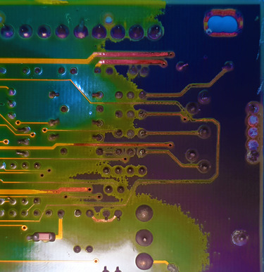
The bad thing is that the battery had leaked and severely damaged the circuit in its vicinity.
I cleaned it in a general way but on the damaged part I did it in the following steps: vinegar+baking soda, water+soap+toothbrush, soft acid+toothbrush (some crust remained), water+soap+toothbrush, vinegar+baking soda (neutralizing any remnant of the last acid), water +soap+toothbrush , dry well . now you can taste the surface with your own tongue, taste nothing, the Ph is 7, totally neutral,
In the images, how it turned out. The images have been digitally treated to highlight details, contrasts and colors, making it easier to assess damage (those here are scaled down for vogons attach).
You can see that some lines have disappeared, although at the bottom they are not so bad, maybe just tinning is enough.
As you see, this is a work for "necroware" (I'll have to find and raise my inner equivalent )
Now I need to do some unsoldering and maybe more localized cleaning. The layout of the missing veins can be inferred, but to be sure I´ll need references, a "ground truth".
For this reason, if anyone has a sample of this motherboard, I would appreciate it if you could share images of that part, the best possible images, from the 4 sides at the top and one from the bottom, clearly showing that part of the mb.
Ah!! and some clarification on whether the TX486DLC/E-40GA would actually work on it is appreciated.