VOGONS


First post, by PD2JK

User metadata
Rank Oldbie
Rank
Oldbie

Dear Vogon'ers.

Thanks for clicking this! 😀

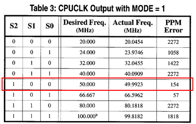
TLDR: How to set the external clock speed at 33 MHz ?

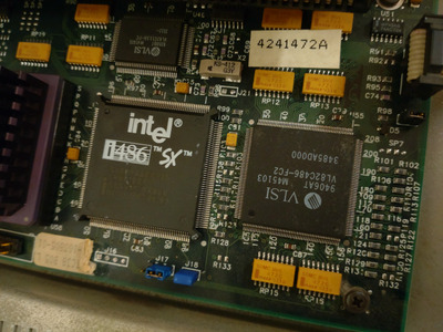
I have this Tulip Vision Line DC Compact with TC38 board, this one.
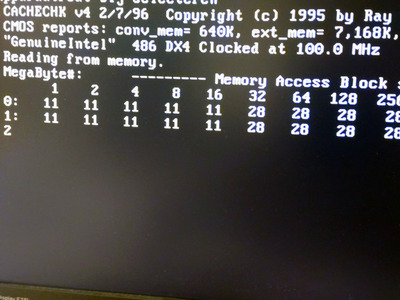
Disabled the onboard SX-25, set the jumper and DX4 Overdrive came to life, at 3x 25 = 75 MHz that is.
I also tried all header-less JP (jumper) connections, it stays at 25MHz.
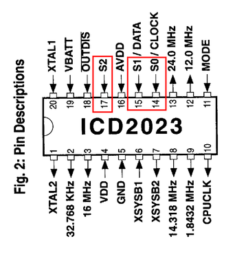
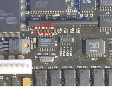
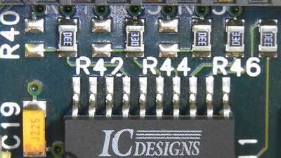
However, there are some SMD resistors between the SX-25 and VLSI VL82C486 (built-in clock generator), maybe these are configureable?

DSC_7017.JPG
Filename
DSC_7017.JPG
File size
1.33 MiB
Views
752 views
File license
Public domain

Could it be that the external clock speed is determined by the BIOS? I can't find any speed setting, only fast/slow processor and ISA bus speed (8 or 6.2 MHz)

I hope we can get this CPU at 100 MHz! 😁

i386 16 ⇒ i486 DX4 100 ⇒ Pentium MMX 200 ⇒ Athlon Orion 700 | TB 1000 ⇒ AthlonXP 1700+ ⇒ Opteron 165 ⇒ Dual Opteron 856

Reply 1 of 9, by rmay635703

User metadata
Rank Oldbie
Rank
Oldbie

Have you identified what all the jumpers do?

[UPDATE 4 / DONE] The journey of Tulip Vision Line DC 486sx TC35

There is bound to be 1 or 2 near the clock generator for setting FSB

Tulip Vision Line DC 486dx TC38 Restoration [Update 5] Finished

Re: Dutch members: Tulip Vision Line dt 4/66 (486) CPU jumper help?

Yep, gotta modify the signals to the clock generator, Tulip had 5 different motherboards variations for your model

Last edited by rmay635703 on 2023-11-24, 15:51. Edited 3 times in total.

Reply 2 of 9, by PD2JK

User metadata
Rank Oldbie
Rank
Oldbie

J16 = unknown, closed 1-2 and 3-4. No difference.
J17 = closed 1-2, no difference. 2-3 must always be closed according to the manual
J18 = when Overdrive R installed, closed since it's a DX4ODPR100 I guess. When open, doesn't boot.
J21 = closed, no difference. X2 looks like an RTC oscillator.

Thanks for replying! 😀

i386 16 ⇒ i486 DX4 100 ⇒ Pentium MMX 200 ⇒ Athlon Orion 700 | TB 1000 ⇒ AthlonXP 1700+ ⇒ Opteron 165 ⇒ Dual Opteron 856

Reply 3 of 9, by Thermalwrong

User metadata
Rank Oldbie
Rank
Oldbie

Looking on the retroweb, the board shots aren't great but I think I understand how the clock generator is set up now, the pictures were high enough res that I can make out where the traces are at least.
The ICD2023sc has three pins that are either pulled high or low to select which frequency to run at. Let's ignore the programmable frequency modes that the clock generator can operate in, I don't think it's doing that:

icd2023sc-stuff.png
Filename
icd2023sc-stuff.png
File size
36.52 KiB
Views
641 views
File license
CC-BY-4.0

Currently you've got 25MHz FSB correct? So it should be the 50MHz value since FSB is usually clk divided by 2 for actual CPU FSB:

icd2023-clocktable.png
Filename
icd2023-clocktable.png
File size
40.55 KiB
Views
641 views
File license
CC-BY-4.0

Zooming all the way into this picture on the retroweb I could just about make out that there are joins between
R40 & R41, which seems to link to S2
R42 & R43, looks like that goes to S1
R44 & R45, looks like that goes to S0

icd2023sc2.jpg
Filename
icd2023sc2.jpg
File size
168.27 KiB
Views
641 views
File license
CC-BY-4.0

My thinking is that a resistor put at R40 will pull the signal low giving S2 a value of "0", while putting a resistor at R41 will pull it high giving it a value of "1"
The layout doesn't make sense for them all to be + then - in order or whatever, maybe the locations are swapped for convenience of PCB layout.

Can you measure the upper side of the resistors & pads present at the top where you see the silkscreen for R41, just by the pins of that ZIPP video memory. Those should link to either 5V or Ground.

If R44 & R45 are linked, potentially you can just move the resistor from R44 onto R45 and that should give you 33MHz FSB. But it's a good idea to verify this first 😀

Reply 4 of 9, by PD2JK

User metadata
Rank Oldbie
Rank
Oldbie

That is some really valuable information! I'll get to it as soon as possible and of course let you know the outcome.

i386 16 ⇒ i486 DX4 100 ⇒ Pentium MMX 200 ⇒ Athlon Orion 700 | TB 1000 ⇒ AthlonXP 1700+ ⇒ Opteron 165 ⇒ Dual Opteron 856

Reply 5 of 9, by PD2JK

User metadata
Rank Oldbie
Rank
Oldbie

Update: added clearer picture of the resistors.

Hmm, resistor R44 is already at R45. So I'm going to move it back to R44. 😁

It's an educated guess that the board from your picture was already configured for 33MHz external speed CPU's, i.e. an ordinary DX 33.

Attachments

  • PHO00020.JPG
    Filename
    PHO00020.JPG
    File size
    88.5 KiB
    Views
    508 views
    File comment
    microscope photo
    File license
    Public domain
Last edited by PD2JK on 2023-11-27, 13:06. Edited 3 times in total.

i386 16 ⇒ i486 DX4 100 ⇒ Pentium MMX 200 ⇒ Athlon Orion 700 | TB 1000 ⇒ AthlonXP 1700+ ⇒ Opteron 165 ⇒ Dual Opteron 856

Reply 6 of 9, by PD2JK

User metadata
Rank Oldbie
Rank
Oldbie

Measuring pin 10 (CPUCLK), and yes indeed 50 MHz:

SDS00001.png
Filename
SDS00001.png
File size
32.75 KiB
Views
492 views
File comment
scope image
File license
Public domain

i386 16 ⇒ i486 DX4 100 ⇒ Pentium MMX 200 ⇒ Athlon Orion 700 | TB 1000 ⇒ AthlonXP 1700+ ⇒ Opteron 165 ⇒ Dual Opteron 856

Reply 7 of 9, by PD2JK

User metadata
Rank Oldbie
Rank
Oldbie

Well, looks like it's working. I'm not 100% happy with the soldering, but those resistors are _tiny_.

DSC_7071.JPG
Filename
DSC_7071.JPG
File size
1.3 MiB
Views
453 views
File license
Public domain

That proves again that I am not an SMT pick and place machine.

What matters, is the result!

SDS00002.png
Filename
SDS00002.png
File size
28.26 KiB
Views
454 views
File license
Public domain

i386 16 ⇒ i486 DX4 100 ⇒ Pentium MMX 200 ⇒ Athlon Orion 700 | TB 1000 ⇒ AthlonXP 1700+ ⇒ Opteron 165 ⇒ Dual Opteron 856

Reply 8 of 9, by PD2JK

User metadata
Rank Oldbie
Rank
Oldbie

And we have a full speed DX4 at work!

A very big thanks to Thermalwrong for pointing, no kicking me in the right direction!

DSC_7079.JPG
Filename
DSC_7079.JPG
File size
1.26 MiB
Views
426 views
File license
Public domain

i386 16 ⇒ i486 DX4 100 ⇒ Pentium MMX 200 ⇒ Athlon Orion 700 | TB 1000 ⇒ AthlonXP 1700+ ⇒ Opteron 165 ⇒ Dual Opteron 856

Reply 9 of 9, by Thermalwrong

User metadata
Rank Oldbie
Rank
Oldbie

That's great 😀 Thanks for the hi-res pic of the PLL area, that did confirm that what I said looks to be correct. Those resistors look to be 33 ohms so they're not far from being jumpers.

Interesting that the picture I was referencing on retroweb already showed the 33MHz PLL configuration, that makes it good for future reference hehe.