VOGONS


First post, by NHVintage

User metadata
Rank Newbie
Rank
Newbie

So.. I done messed up. I was working on the Acer-mobo 486 yesterday, and it had a small coin battery (dime sized, not nickel sized like usual) in a vertical holder, which was already loose. I went to either pull it or at least see how it was connected and either it was REALLY lose or I am way too clumsy because the battery and the two tabs that turned out to be soldered to it broke off. Now, when I power up the pc, all I get is repeated, long, slow, razzberry type buzzes - not even beeps. I have to assume that this is because the battery is dead (and gone) but there is an external battery connnector right next to it (which isn't in the documentation EDIT: It's JP5 in the documentation) and when I try connecting a battery to it, I still get those long slow razzberries (EDIT: that battery was a bit of a kluge to test the basic theory of it working, but just in case, I've ordered an actual ER17/33 battery with the right connector which will get here in the next week). Can anyone share more information what exactly is going on here and what I might be able to do to fix it?

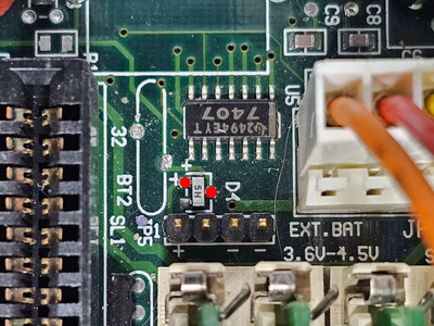
Closeup of the external battery connector and BT2, the two solder points on the long oval is where the battery was soldered on. https://www.dropbox.com/scl/fi/b0t2ja9x68uipn … q6cw50e0km&dl=0

Here's a short video of the startup of the pc so you can hear that weird buzzing beep repeating, and see the post code that it stops at on my ISA diagnosing card.
https://www.dropbox.com/scl/fi/4j5izdonx0bcl5 … shei8opxfx&dl=0

If you're into shortwave radio and numbers stations: it sounds EXACTLY like "The Buzzer". 😁

Reply 1 of 15, by NHVintage

User metadata
Rank Newbie
Rank
Newbie

On the chance that the buzzes are, despite them sounding different, from memory having an issue that just happens to coincide with the cmos battery incident - the SIMMS are right next to where the CMOS battery is, and long beeps are usually signs of a RAM issue - I pulled all the SIMMs, cleaned their contacts, and cleaned the slots as well. Unfortuately that didn't help. I also tried other SIMMS, and no dice. I made sure the four slots were filled (out of 😎 as the board requires all four in the bank be filled.

It does occur to me that even if the CMOS battery is dead/gone the PC should still boot, just not remember its BIOS config or the time and date. It is starting to boot: I see the 05 and 06 and 0C and 0D boot codes before it stops (IIRC). I'm just not sure what to do next. I tried pulling out all the cards to see if that helped, no change.

Reply 2 of 15, by analog_programmer

User metadata
Rank Oldbie
Rank
Oldbie

I have one motherboard (Zida Tomato 5STX) that doesn't boot at all without healthy CMOS battery. And I also have an old Asus notebook that also doesn't boot at all without healthy CMOS battery. So, first try to attach external battery or try to repair this torn battery-holder.

from СМ630 to Ryzen gen. 3
engineer's five pennies: this world goes south since everything's run by financiers and economists
this isn't voice chat, yet some people, overusing online communications, "talk" and "hear voices"

Reply 3 of 15, by NHVintage

User metadata
Rank Newbie
Rank
Newbie

I've tried a couple of jury-rigged batteries to the external battery connector with no luck, let's hope the actual battery that I ordered will do the job instead. I traced out the battery circuitry, the positive pin on the external battery connector leads to one of 3 connections of what looks like a resistor that has '5M' printed on it, but is labelled D4, suggesting its maybe a diode (see the picture linked below). There are two sets of battery mount pads, one for the battery that snapped off, and another that would take a flat CR2023 battery holder; their positive pads lead to a second connection on that D4 device. beyond that I don't know where the circuit goes. I don't think therefore there is a jumper that chooses internal or external battery since both the batteries and external pins lead to that same D4 device, and I suspect then goes out D4's third connection to the rest of the PC, with no jumpers between the power sources and D4.

A plan B if the external battery doesn't work is to mount a CR2023 battery holder where there are pads for it and see if that works better.

<url>https://www.dropbox.com/scl/fi/1j5rfqya ... &dl=0</url>

Reply 4 of 15, by analog_programmer

User metadata
Rank Oldbie
Rank
Oldbie

On some (if not all) old 386/486 mobos there is a jumper on that 4-pin external battery connector (on pins 2-3) when used on-board battery. Right now I can't find the most widespread diagram for this batteries part of these old motherboards, but when I have more time to dig I'll give a link or I'll draw one.

from СМ630 to Ryzen gen. 3
engineer's five pennies: this world goes south since everything's run by financiers and economists
this isn't voice chat, yet some people, overusing online communications, "talk" and "hear voices"

Reply 5 of 15, by NHVintage

User metadata
Rank Newbie
Rank
Newbie

Awesome, thanks! As I said, I did continuity testing on the external and battery locations. The 4-pin external connector's negative pins (3 & 4) have continuity to the negative pads of both battery locations. Pin 2 has no connectivity to anything I can find. and Pin 1, the positive pin, has continuity to D4 pin 1. The positive pads of both battery positions have continuity to D4 pin 2. I'll modify my test battery setup to jumper pins 2 and 3 and keep the positive battery to pin 1 and negative to pin 4. I probably won't get to that until tomorrow though. Thanks for your help!

A new AT power supply has arrived, too. I needed a backup on hand anyway as my last one went into another project, so I may try that new PS on this machine, too, as I'm well aware of the weirdness that a bad PS can create.

Reply 6 of 15, by NHVintage

User metadata
Rank Newbie
Rank
Newbie

I got the actual backup battery in and ran all these tests:
1) backup battery plugged in the 4-pin header: fail (repeat buzz no bios boot)
2) jumper 2-3 on the 4-pin header, pos and neg in 1 and 4: fail
3) reverse pos and neg from battery to header, just in case board is mislabelled: fail
4) try booting with brand new power supply: fail
5) battery negative to negative pin on header (which has continuity with negative battery holder pads on mobo), positive battery via test probe to positive pad on mobo for battery holder: SUCCESS!

So it appears the only way I'll get the PC to boot up is by replacing the CR2025 lithium battery that snapped off with a new battery mount and coin battery. apparently the external battery connector is non-functional. There is no jumper marked for external battery on either the board or in the documentation, and continuity testing to the 'factory set do not alter' jumpers showed no connectivity to any positive or negative battery pad/header pins. I also peeked around for any unpopulated jumper pads that might allow the external pins to work, without luck.

Kinda sucks because it means I'll have to remove the mobo from the case and then be really careful soldering a new holder or pin where I need it, as there's other pads for other components like 1/16th inch from the battery pads and I'm not the greatest at soldering, but nothing for it I guess but to try. I'll keep you posted on how that goes.

Picture showing the 'playing field' where the two battery mount pad sets and the 4-pin external header is, along with the D4 diode (tentatively identified as a zener diode) and neighboring components. You can see the traces from the positive pin on the external header to the 'left end' positive diode pad, and the traces from the coin battery positives to the pad above the middle of that diode. I figured there would be continuity between that middle pad and the 'negative' pad of the diode, indicating the diode was bypassed for the coin batteries, but nope.
https://www.dropbox.com/scl/fi/0axv92aqfzq6jy … xz7l95o30g&dl=0

Reply 7 of 15, by analog_programmer

User metadata
Rank Oldbie
Rank
Oldbie

Ok, sorry for the delay. Just now I've managed to find some spare time.

I found the diagram for the typical external battery connector plus on-board rechargeable battery in this topic: Better understanding barrel battery charging circuit

Just for clarification I added where the COMS is connected in jakethompson1's diagram:

extbatt.jpg
Filename
extbatt.jpg
File size
24.75 KiB
Views
760 views
File comment
Ext. batt. connector
File license
Fair use/fair dealing exception

I'v checked my 386 board and the diagram is practically the same, except that instead of D1 and D2 with related resistors (150 and 33 Ohm) there are traces on my mobo, and also the second 33 Ohm resistors after the D4 is placed directly on the path to the CMOS.

Here are the diagram for my 386 mobo:

myextbatt.jpg
Filename
myextbatt.jpg
File size
20.4 KiB
Views
742 views
File comment
Ext. batt. my 386 mobo
File license
Fair use/fair dealing exception

For normal operation i.e. the COMS is powered from+5V directly or from on-board rechargeable battery (when the board is powered off) and external battery not connected a jumper must be inserted between 2nd and 3rd pin of the external connector.

I hope this will help you to figure out how the external battery connector works.

P.S. I see that you've managed to boot the motherboard with battery attached. That's good, but if you want to use some regular (non-rechargeable) CR2032 battery, you have to do some modification to the circuit.

P.S.2 Forget this, your motherboard's schematic is totally different.

Last edited by analog_programmer on 2023-12-02, 21:23. Edited 1 time in total.

from СМ630 to Ryzen gen. 3
engineer's five pennies: this world goes south since everything's run by financiers and economists
this isn't voice chat, yet some people, overusing online communications, "talk" and "hear voices"

Reply 8 of 15, by NHVintage

User metadata
Rank Newbie
Rank
Newbie

Thanks for taking the time to look this up. I looked around your diagrams and the thread, and I don't think that they apply to my board. the reason is I have a separate 2 pin header for CMOS clearing: open for normal, closed to reset it. it's nestled between a couple of the ISA slots, which is about 5 inches from the 'ext bat' header. Both pin 3 and 4 on my external battery header have continuity to ground and are marked negative. Pin 1 on mine is positive, and pin 2 doesn't appear to have any connection - I checked for continuity between the cmos reset pins and the four external battery header pins and no joy. I did try to jumper pin 2 and 3 on the battery header while the battery was connected to 1 and 4, and that didn't work either.

Unfortuanately, while mobo diagrams and jumper listings have been found, no 'user guide' seems to be out there to explain things in detail, and I've looked for Acer service manuals no luck either, so if there is some special thing that needs to be done to get an external battery to work, I'm not sure what it could be.

Reply 9 of 15, by analog_programmer

User metadata
Rank Oldbie
Rank
Oldbie

So, your motherboard it's not with conventional CMOS rechargeable battery schematic, but some Acer's design. Now I see that on your ext. batt. connector pins 3 and 4 are both ground, pin 2 is not connected, and pin 1 is positive to external battery and also through diode (marked as D4) to positive terminal/pad of on-board battery.

NHVintage wrote on 2023-12-02, 17:18:

I got the actual backup battery in and ran all these tests:
1) backup battery plugged in the 4-pin header: fail (repeat buzz no bios boot)
5) battery negative to negative pin on header (which has continuity with negative battery holder pads on mobo), positive battery via test probe to positive pad on mobo for

This is very strange.

If original on-battery is not rechargeable the things are simple. In this case just connect external battery to pins 1 and 3 (or 4) and that's it (case 1) ). But I see that this doesn't happen.

In case 5) you're connecting external battery through the diode (D4 from the positive pad of on-board battery) to pin 1 and only this way the motherboard boots normally. Correct me, if I'm wrong.

Is the voltage of the external battery more than 4.5 V (marked on the board as max. value)? If it is for example 6 V, when this 6 V battery is connected through the diode (D4) there's some voltage drop and then on pin 1 there's voltage close to marked maximum value of 4.5 V.

from СМ630 to Ryzen gen. 3
engineer's five pennies: this world goes south since everything's run by financiers and economists
this isn't voice chat, yet some people, overusing online communications, "talk" and "hear voices"

Reply 10 of 15, by NHVintage

User metadata
Rank Newbie
Rank
Newbie

This whole thing is strange! 😁
On 5, I used a probe to connect the battery negative to one of the negative pins on the external battery header because it was convenient, it has connectivity to negative on both of the on-board battery pad locations so it didn't matter if I put it there or the pads, but its a lot easier keeping one probe point (the positive) in place on a pad while booting the pc than it is to keep two probes in place. If I put positive power to either of the onboard battery positive pads (it has two locations, one for a button battery edge on, another for either a barrel or flat button connector), then it boots. It gets really weird that the battery positive pads go to a THIRD pad on D4. if it's a Diode, it only has 2 connecting points, it's not a transistor. and there is no connectivity between those 2 positive pads on the diode (one of which leads to the on board +'s, the other to the external battery +), nor a connection between either of those and the third pad on the diode. I'm stumped.

The battery is a 3.6V ER17: <url>https://m.media-amazon.com/images/I/51q ... _.jpg</url>

Reply 11 of 15, by analog_programmer

User metadata
Rank Oldbie
Rank
Oldbie

From what I see on the picture with the part near the external battery connector and your explainations this must be the simplified circuit diagram if on-board battery is non-rechargeable CR2032:

extbatt.jpg
Filename
extbatt.jpg
File size
11.74 KiB
Views
673 views
File comment
ext.batt.
File license
Fair use/fair dealing exception

The diode D4 seems to be two diodes in one package with common cathode.

It's not clear where the "clear CMOS" jumper pins are connected.

from СМ630 to Ryzen gen. 3
engineer's five pennies: this world goes south since everything's run by financiers and economists
this isn't voice chat, yet some people, overusing online communications, "talk" and "hear voices"

Reply 12 of 15, by NHVintage

User metadata
Rank Newbie
Rank
Newbie

As good a guess as any but it doesn't help me get the external battery working. I might just see if I can get away with soldering a post in the + of one the on board battery pads, then connect the external battey + to it like I tested. Plus would make it easier to rig a modification to the circuit if needed.

Reply 13 of 15, by NHVintage

User metadata
Rank Newbie
Rank
Newbie

So a followup, and good news. I wasn't satisfied with the CMOS jumper connection being unknown so I tested continuity between each of its two pins and the positive pads of the onboard battery, and got a positive from one of them. So, I hooked the external battery + to that pin, and the external battery - to one of the negative posts on the external battery connector, and it works! picture below. I've had the PC running for a couple hours now and the battery is still cool, so it doesn't look like there's a charging current to worry about either. configurations seem to be staying put in the BIOS. I'm going to secure the battery and cables and call it solved.

CMOS jumper on the left, and the 4-pin header on the right. FWIW I also tried keeping the CMOS jumpers bridged and using the + on the external battery connection, and that didn't work.
<URL>https://www.dropbox.com/scl/fi/vmda93sx ... &dl=0</URL>

Reply 14 of 15, by analog_programmer

User metadata
Rank Oldbie
Rank
Oldbie
NHVintage wrote on 2023-12-04, 15:18:

So a followup, and good news. I wasn't satisfied with the CMOS jumper connection being unknown so I tested continuity between each of its two pins and the positive pads of the onboard battery, and got a positive from one of them. So, I hooked the external battery + to that pin, and the external battery - to one of the negative posts on the external battery connector, and it works! picture below. I've had the PC running for a couple hours now and the battery is still cool, so it doesn't look like there's a charging current to worry about either. configurations seem to be staying put in the BIOS. I'm going to secure the battery and cables and call it solved.

CMOS jumper on the left, and the 4-pin header on the right. FWIW I also tried keeping the CMOS jumpers bridged and using the + on the external battery connection, and that didn't work.
<URL>https://www.dropbox.com/scl/fi/vmda93sx ... &dl=0</URL>

Maybe I'm wrong with the last drawing, so the diode actually is in opposite position and the CMOS connection is between the diode and the on-board battery trace. The only thing that comes to mind is to check the diode D4 with multimeter if it is burned-out (shows very high resistance in both directions) between its pins soldered to PCB's traces.

Check D4 in these two points, if there is some conductivity (very low resistance) in only one direction (thus it's healthy):

wOg2GfPo.jpeg
Filename
wOg2GfPo.jpeg
File size
1.22 MiB
Views
540 views
File license
Fair use/fair dealing exception

from СМ630 to Ryzen gen. 3
engineer's five pennies: this world goes south since everything's run by financiers and economists
this isn't voice chat, yet some people, overusing online communications, "talk" and "hear voices"