First post, by Rolling
Hi guys,
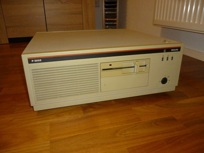
i recently got a a Philips P3202 Pc and i'm trying to bring it back to live! 😀
Thanks to SDumas (see Re: vintage scanned manuals) we have the "Inside your P3202" manual which is a great start for working with the machine.
Sadly there is no part mentioning CMOS settings. Searching for some board data and downloads i found this page:
https://www.maerivoet.org/index.php?page=elec … ics-p3204-80286
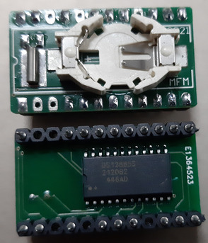
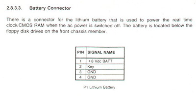
The board has an Dallas RTC Chip (with dead coin cell of course) but seems to also have an "battery connector" with the following pinout:
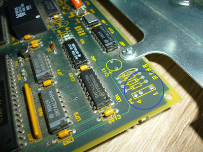
I'm thinking of using an external battery instead of dealing with the RTC-Chip, but what i'm a little bit worried about is that there is no jumper to disable the internal battery. On my other 286 machines there was always a way to disable internal battery. Looking at the board there also seem to be no diodes beside the P1 external battery pin header:
Do you think it is safe to hook up a 6V power supply (f.e. 4x1.5V AA batteries) to the board?
What i also don't get is what pin 2 is supposed to be. The machine has a keylock mechanic to start. Looking at the documentation i assume i need to connect some line from the keylock to the board to recognize when the system is turned off and hold the CMOS settings. But on the board itself there only seems to be pin 1 (+6V), pin 3 and 4 (GND).
Maybe someone can give me an advice on how to proceed without frying anything 😀