VOGONS


First post, by Rolling

User metadata
Rank Newbie
Rank
Newbie

Hi guys,

i recently got a a Philips P3202 Pc and i'm trying to bring it back to live! 😀

pc.JPG
Filename
pc.JPG
File size
155.74 KiB
Views
694 views
File license
Public domain

Thanks to SDumas (see Re: vintage scanned manuals) we have the "Inside your P3202" manual which is a great start for working with the machine.

Sadly there is no part mentioning CMOS settings. Searching for some board data and downloads i found this page:
https://www.maerivoet.org/index.php?page=elec … ics-p3204-80286

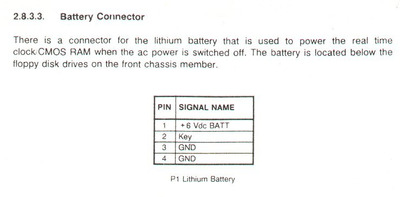
The board has an Dallas RTC Chip (with dead coin cell of course) but seems to also have an "battery connector" with the following pinout:

p3202-battery-connector.jpg
Filename
p3202-battery-connector.jpg
File size
31.32 KiB
Views
694 views
File license
Public domain

I'm thinking of using an external battery instead of dealing with the RTC-Chip, but what i'm a little bit worried about is that there is no jumper to disable the internal battery. On my other 286 machines there was always a way to disable internal battery. Looking at the board there also seem to be no diodes beside the P1 external battery pin header:

P1250962.JPG
Filename
P1250962.JPG
File size
625.43 KiB
Views
694 views
File license
Public domain

Do you think it is safe to hook up a 6V power supply (f.e. 4x1.5V AA batteries) to the board?

What i also don't get is what pin 2 is supposed to be. The machine has a keylock mechanic to start. Looking at the documentation i assume i need to connect some line from the keylock to the board to recognize when the system is turned off and hold the CMOS settings. But on the board itself there only seems to be pin 1 (+6V), pin 3 and 4 (GND).

Maybe someone can give me an advice on how to proceed without frying anything 😀
Reply 1 of 14, by Nexxen

User metadata
Rank Oldbie
Rank
Oldbie

In some of my boards the two grouped pins are ground and the the lonely one is +.
Check with a multimeter.
Maybe diodes need to be added. IDK

For 6V I don't know.

PC#1 Pentium 233 MMX - 98SE
PC#2 PIII-1Ghz - 98SE/W2K

Reply 4 of 14, by konc

User metadata
Rank l33t
Rank
l33t

The "key" (missing) pin doesn't have anything to do with the keyboard, it's there so that you don't mix up VDC and GND. The idea is that the connector wouldn't allow you to plug it the other way around, now of course you don't have the actual pins and the battery connector for this to work.

Most external battery connectors were meant for non-rechargeable batteries, but for machines of that age you can't be certain. Isn't it fairly simple though to measure if charging current reaches these pins?

Reply 5 of 14, by Rolling

User metadata
Rank Newbie
Rank
Newbie

I checked it - Pin 3 & 4 are GND and Pin 1 is +, as mentioned in the manual and by Nexxen. There seems to be no charging current.

I'm still not sure about the voltage though. I've had 286 systems which needed 6V to hold CMOS settings, but all of them had some diodes beside the ext. battery pin header.

Since the spots for diodes on this board (D3-D6) aren't populated and even one joint at D6 is bridged with wire i'm not sure, if i can just put 6V there.

Reply 7 of 14, by weedeewee

User metadata
Rank l33t
Rank
l33t

.
Do any of you think that adding an external battery by adding an unpopulated external battery connector to a mainboard that uses a "DS1287 RTC with integrated battery and no external battery pins" will have the effect you desire of keeping the RTC running and the 'cmos bios memory' backed up ?
.

You probably can, but you'll need to add the diodes that stop the battery from backfeeding into the whole system and charging the battery and remove the jumper wire that currently feeds the dallas and replace it with a diode. (likely the one that stops the backfeeding the battery to the whole system.

Right to repair is fundamental. You own it, you're allowed to fix it.
How To Ask Questions The Smart Way
Do not ask Why !
https://www.vogonswiki.com/index.php/Serial_port

Reply 8 of 14, by TheMobRules

User metadata
Rank Oldbie
Rank
Oldbie

The DS1287 has an internal battery that is not accessible at all via the pins on the chip unlike a DS1285 (in fact, the DS1287 is essentially a DS1285 with the battery pins folded up and connected to a battery + an oscillator crystal, which are sealed with a plastic cover). So there is no way to disable the internal battery and connect it to an external source without hacking the chip.

Now, it is possible your motherboard has a circuit that provides external battery power to the Vcc input of the Dallas chip (pin 24) via the connector you show in the picture. However, unlike the internal battery this would require a voltage in the 4.5 - 5.5V range, which means you need an external battery of either 6V + one or two diodes to lower the voltage, or 4.5V without any diodes. But the fact that the external battery connector and diodes are unpopulated on this board makes me suspicious, I think those are probably intended for other variants of the board that use RTC/CMOS without an integrated battery.

In any case, you should trace the external battery pads and see where they end up, some pics of the board may also be of help.

Reply 9 of 14, by SDumas

User metadata
Rank Newbie
Rank
Newbie

i didn't see the Dallas chip... (blind!...blind!...blind!...).

TheMobRules is right.So in this case it is easier to solve...

Mod the Dallas chip or buy a new one if available.

That's what I would do if the computer was mine.

Reply 10 of 14, by Rolling

User metadata
Rank Newbie
Rank
Newbie

Ok, i traced the external battery pins to the dallas chip and they make no sense. VCC is connected to Ground and some other pins don't add up either. I guess TheMobrules is right - there are probably more components missing or the header is for another variant of the board. I guess i don't want to tinker with it, since i don't want to destroy the board. I just wanted to see if there's an alternative to modding the chip.

*sigh*, so it's grinding down the Dallas chip again. Can't tell you how much i hate these things! 😁

Thanks for your help!

Reply 11 of 14, by SDumas

User metadata
Rank Newbie
Rank
Newbie

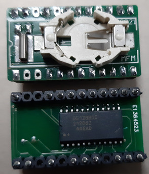
Or get one of these if you can find it in your country.

There are some people who make and sell it, for example "Necroware" i think...

Attachments

  • RTC.jpg
    Filename
    RTC.jpg
    File size
    771.88 KiB
    Views
    517 views
    File license
    Fair use/fair dealing exception

Reply 12 of 14, by weedeewee

User metadata
Rank l33t
Rank
l33t
Rolling wrote on 2023-12-23, 19:01:

Ok, i traced the external battery pins to the dallas chip and they make no sense. VCC is connected to Ground and some other pins don't add up either. I guess TheMobrules is right - there are probably more components missing or the header is for another variant of the board. I guess i don't want to tinker with it, since i don't want to destroy the board. I just wanted to see if there's an alternative to modding the chip.

*sigh*, so it's grinding down the Dallas chip again. Can't tell you how much i hate these things! 😁

Thanks for your help!

From what little I gather, there is a way to mod the mainboard.
Care to share what you learnt from tracing the board?

my guess from the photo of your board would be that you need to, at least, replace the jumperwire on position D6 with a diode, and add, at least, on other diode in, I guess, one of either D3,D4 or D5 to stop the battery from being charged when the system is on.

Right to repair is fundamental. You own it, you're allowed to fix it.
How To Ask Questions The Smart Way
Do not ask Why !
https://www.vogonswiki.com/index.php/Serial_port

Reply 13 of 14, by Rolling

User metadata
Rank Newbie
Rank
Newbie

To get the system up and running i I just drilled the Dallas-Chip and soldered an external coin cell holder to the chip.

I don't know if that's simple, because D3-D5 seem to have different connections to the Dallas Chip. During tracing i found f.e. that even the plus pin on the battery header is connected to ground on the Dallas. At first i thought this is caused by the bridge on D6, but even without it, it's grounded. One trace also runs to an unpopulated capacitor. Maybe it would be quite easy to mod but i don't trust the board, it seems there are some other shenanigans going on.

Anyway - i'll keep this approach in mind and will try to have a deeper look into it. Thanks again for your help!

Reply 14 of 14, by TheMobRules

User metadata
Rank Oldbie
Rank
Oldbie
Rolling wrote on 2023-12-23, 23:10:

I don't know if that's simple, because D3-D5 seem to have different connections to the Dallas Chip. During tracing i found f.e. that even the plus pin on the battery header is connected to ground on the Dallas. At first i thought this is caused by the bridge on D6, but even without it, it's grounded. One trace also runs to an unpopulated capacitor. Maybe it would be quite easy to mod but i don't trust the board, it seems there are some other shenanigans going on.

On boards without Dallas type chips there is usually a circuit for switching the supply for the RTC/CMOS between the PSU and battery power when turning on and off the system respectively. This involves some parts like diodes, resistors, transistors and capacitors and all of that stuff was probably left unpopulated on your board since the DS1287 does that switching internally.