First post, by jnemo2004
Rank
Member
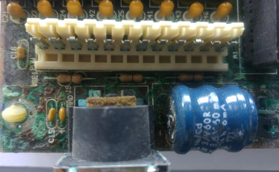
Dear Sirs, I received this motherboard damaged by corrosion.
Dear Sirs, I received this motherboard damaged by corrosion.
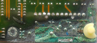
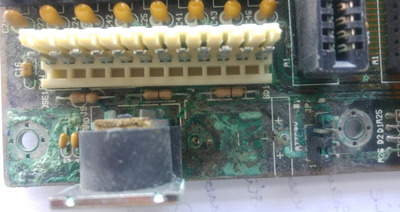
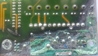
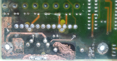
I removed damaged components and cleaned the board.
The following components were removed
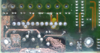
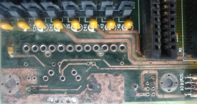
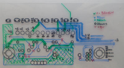
The board tracks and the schematic .
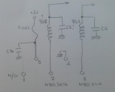
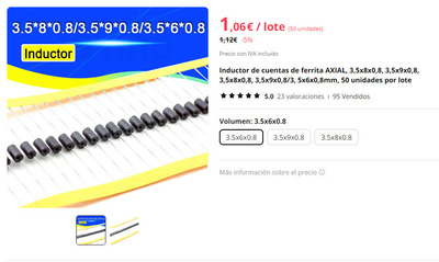
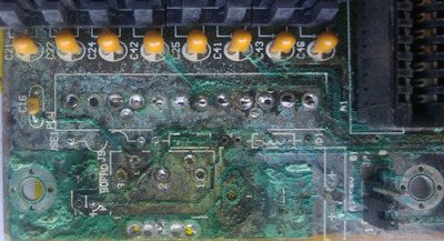
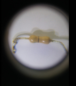
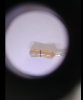
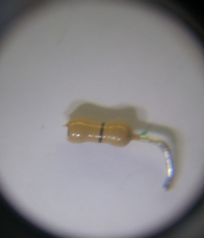
As you can see, there are three components labeled in the board as, FUSE1 (this is in good condition), BD1 (broken) and BD2? (broken) but the three are the same. BD1 and BD2 need to be replaced but I do not know which components they are, maybe inductors? but a fuse (FUSE1) is the same. FUSE1 can be used but BD1 and BD2 my question: I have two inductors from a Pentium I mobo (see picture attached) can I use them? or maybe you help me to identify these two BD1 and BD2 and I will try to by new ones.
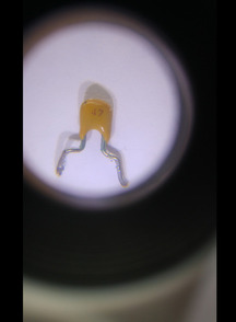
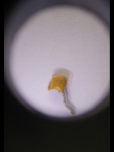
There are two capacitors C4 and C5?, C5? is broken and C4 it is to replace it. The capacitors are identified written on them as 47. My question: Can I use ceramic capacitors (the orange discs) ? I also do not know if the figure 47 is nF or pF.
Thank you very much
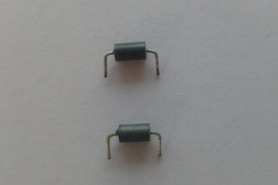
BD1 and BD2 are chokes, a type of inductor used for blocking high frequencies and allowing low frequencies to pass. You can use the ones you salvaged from the pentium board.
It is common to see board makers cheap out and replace the fuse with a wire bridge or 0 Ohm resistor.
For capacitors you can use 47pF ceramic disks.
You did an excelent job sofar!
jnemo2004 wrote on 2024-02-01, 08:29:As you can see, there are three components labeled in the board as, FUSE1 (this is in good condition), BD1 (broken) and BD2? (broken) but the three are the same. BD1 and BD2 need to be replaced but I do not know which components they are, maybe inductors? but a fuse (FUSE1) is the same. FUSE1 can be used but BD1 and BD2 my question: I have two inductors from a Pentium I mobo (see picture attached) can I use them? or maybe you help me to identify these two BD1 and BD2 and I will try to by new ones.
There are two capacitors C4 and C5?, C5? is broken and C4 it is to replace it. The capacitors are identified written on them as 47. My question: Can I use ceramic capacitors (the orange discs) ? I also do not know if the figure 47 is nF or pF.
Thank you very much
These are ferrite beads, you can use almost any of them, or also you can use 10 Ohm resistors instead. Along with capacitors (usually 47p) they filter out radio interference induced to the cable from keyboard serial data/clock. Yes, you can use MLC or ceramic disc capacitors, no big deal.
As for the fuse, you can put a 47 Ohm 1/2W resistor there, it will work perfectly as a current limiting part you can put a 1/4W zero Ohm resistor, a 350 mA fuse, another ferrite bead, or just a thin piece of wire there.
Thank you very much. Great support from your side! Regards.
I don't think you can replace the fuse with a 47 Ohm resistor. Use the original fuse if it is still good.
Yeah do not replace the fuse with a resistor. Some older KB draw near 300mA is why typical design is for 500mA iirc. Those fuses are typically a 1amp slow blow but any 1amp will work.
most newer ps2 KB draw about 100mA (aka 47ohm so with a 47ohm in series would only get 2.5v and limited to 50mA) but some older AT KB draw near 300mA iirc.
Is my ohms law correct ? 😀
Hate posting a reply and then have to edit it because it made no sense 😁 First computer was an IBM 3270 workstation with CGA monitor. Stuff: https://archive.org/details/@horun
Dorunkāku wrote on 2024-02-01, 23:31:I don't think you can replace the fuse with a 47 Ohm resistor. Use the original fuse if it is still good.
What is the rationale here? If we are going to remove the protection just bodge it with 0R, what good would 47R do here?
Retronautics: A digital gallery of my retro computers, hardware and projects.
You should use the original parts and materials where possible...
MLCC caps, not basic ceramic.
Fuse, not 0-ohm or 47r...
Original chokes
For a quick test to see if the motherboard works in general you can use a link for the fuse & chokes (unless the chokes help generate the frequency) and no caps at all...
Thank you very much. You (all) are given a great support.
MikeSG wrote on 2024-02-02, 07:32:You should use the original parts and materials where possible... […]
You should use the original parts and materials where possible...
MLCC caps, not basic ceramic.
Fuse, not 0-ohm or 47r...
Original chokesFor a quick test to see if the motherboard works in general you can use a link for the fuse & chokes (unless the chokes help generate the frequency) and no caps at all...
The problem is that I am not able to identify the original chokes to order a news one.
Those inductors: From a Micro 386 board schem and another schematic the values are similar to this: https://www.digikey.com/en/products/detail/fa … 3001112/8594338 or
https://www.mouser.com/ProductDetail/Fair-Rit … xnPVMh3Dg%3D%3D.
simple low Z chokes, you probably could get by with any up to about 150-180 ohm @100Mhz....
Hate posting a reply and then have to edit it because it made no sense 😁 First computer was an IBM 3270 workstation with CGA monitor. Stuff: https://archive.org/details/@horun
Thank you very much.
Horun wrote on 2024-02-04, 01:56:Those inductors: From a Micro 386 board schem and another schematic the values are similar to this: https://www.digikey.com/en/products/detail/fa … 3001112/8594338 or
https://www.mouser.com/ProductDetail/Fair-Rit … xnPVMh3Dg%3D%3D.
simple low Z chokes, you probably could get by with any up to about 150-180 ohm @100Mhz....
appiah4 wrote on 2024-02-02, 06:07:Dorunkāku wrote on 2024-02-01, 23:31:I don't think you can replace the fuse with a 47 Ohm resistor. Use the original fuse if it is still good.
What is the rationale here? If we are going to remove the protection just bodge it with 0R, what good would 47R do here?
I don’t think the fuse in the keyboard powering circuit is a rational protection from overvoltage or overcurrent. Dozens of 386 motherboards I have, mostly repaired after leaked batteries and other dumpster-related damages confirms that: none of them has fuse there. After all, it’s the task of the PSU to protect the whole computer from overcurrent and overvoltage and every PSU already contains a fuse.
Maybe a fuse in this particular motherboard could be a protection for the MB itself from connecting a power amp or something like that instead of the keyboard.
However, when something’s wrong with the keyboard and it’s causing a short, 100 mA is a reasonable limit for current to not overload the 5V rail and not blow the PSU fuse. That’s why I’m suggesting 47R, taking 100 mA as a reference supply current for keyboards, which I’ve took somewhere on the Internet.
Of course, this replacement in the 1st place is the optional, fast way to test the circuit with some spare resistor laying around and later, order the correct parts, which are btw unknown. It could be even a piece of hair-thin lead from a multilead copper wire, doing the same job. If there are keyboards draining as much as 300 mA, okay, let it be 2W 16Ω instead, but honestly, in this case, a 350 mA fuse could be even cheaper option on the time of manufacturing and that could be the reason to put the fuse there.
The same is with chokes/ferrite beads. Their inductance isn’t printed but they are often replaced with 0R, 10R, 4R7 and other low-resistance resistors on the good half of motherboards and not only motherboards I have, and it’s always exactly the same circuit: data/clock -> RC/LC filter -> track right into pins 1/39 of the KB BIOS. The difference is negligible for the keyboard signals.
Mainly, the same is with bulk caps which can be 10 uF and any higher number, with bypass caps which may be 33n and higher, virtually up to any value, as long as it’s ceramic having low ESR; resistor arrays which usually are acting as pull-ups: 2K2, 4K7, 10K, any reasonably low value for a single replacement, giving <5 mA per pin is fine.
Most of the time, even exact type of TTL IC isn’t critical: HCT, ACT are often work perfectly in place of LS versions which are hard to obtain these days.
So, it’s not as critical as it could he with modern GHz-rated boards with measured lengths of tracks and very high sensitivity to shape of signal edges, or as with power supplies where fuses must be used exactly as specified for real fast protection and not blowing under normal load within specs.
I appreciate all your comments as they are all helpful to me. Thank you so much.
Whomever started with the suggestion of replacing the fuse with a 47 ohm resistor should check up on his knowledge of ohms law.
Especially given the idea of a 100mA current draw (which seems appropriate for a keyboard).
Please calculate the voltage drop that causes.
Right to repair is fundamental. You own it, you're allowed to fix it.
How To Ask Questions The Smart Way
Do not ask Why !
https://www.vogonswiki.com/index.php/Serial_port
I would like to buy these inductors but the values are the dimensions ????
(Sorry, the text are in a bad spanish). How can I translate dimensions to uH or R/Freq.
Thank you ver much
Horun wrote on 2024-02-04, 01:56:Those inductors: From a Micro 386 board schem and another schematic the values are similar to this: https://www.digikey.com/en/products/detail/fa … 3001112/8594338 or
https://www.mouser.com/ProductDetail/Fair-Rit … xnPVMh3Dg%3D%3D.
simple low Z chokes, you probably could get by with any up to about 150-180 ohm @100Mhz....