VOGONS


First post, by jnemo2004

User metadata
Rank Member
Rank
Member

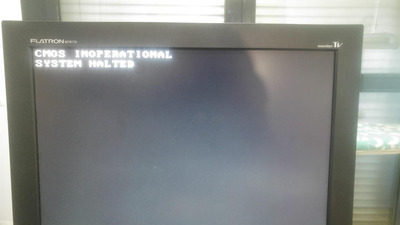
Dear sirs, I just bought this motherboard and I does not work. It stops in CMOS inoperational error.
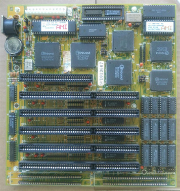
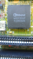
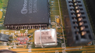
According with the information from the vendor, he got the same error and he tried to solve it changing the IC Winbond W83C201P.
The problem remains and he put back the same IC (???).
Maybe some of you had this problem and maybe you can give any suggestion where to start.
Thank you very much.

Attachments

Reply 1 of 98, by Jo22

User metadata
Rank l33t++
Rank
l33t++

Hi, I'm not sure how exactly to help.

But it seems to me that the BIOS can't access the CMOS RAM that holds the configuration data (floppy type, HDD, etc).

That happens if the RTC (real-time clock) has no power for whatever reason.
If the clock is powerless, its internal RAM is not available, too.

Hm. A workaround eould be to try another BIOS, thus.
Your board has the AMI BIOS, maybe an Award BIOS doesn't halt if the CMOS is dead.
Some BIOSes simply use default values or keep a doublicate of the settings in PC RAM, which survives a reset.

This board has an Winbond W83C201P, too.
But I'm not sure about the other chips, if they're same as on your board.

Re: 80286 BIOS image collection

"Time, it seems, doesn't flow. For some it's fast, for some it's slow.
In what to one race is no time at all, another race can rise and fall..." - The Minstrel

//My video channel//

Reply 2 of 98, by jnemo2004

User metadata
Rank Member
Rank
Member

I understand that first step is to replace the batteries. The board has two CR2016. I have buy new ones.
The vendor, he was doing some tricks with batteries. One of them was covered in the side by isulating tape.

Jo22 wrote on 2024-02-12, 16:58:
Hi, I'm not sure how exactly to help. […]
Show full quote

Hi, I'm not sure how exactly to help.

But it seems to me that the BIOS can't access the CMOS RAM that holds the configuration data (floppy type, HDD, etc).

That happens if the RTC (real-time clock) has no power for whatever reason.
If the clock is powerless, its internal RAM is not available, too.

Hm. A workaround eould be to try another BIOS, thus.
Your board has the AMI BIOS, maybe an Award BIOS doesn't halt if the CMOS is dead.
Some BIOSes simply use default values or keep a doublicate of the settings in PC RAM, which survives a reset.

This board has an Winbond W83C201P, too.
But I'm not sure about the other chips, if they're same as on your board.

Re: 80286 BIOS image collection

Reply 4 of 98, by Murugan

User metadata
Rank Oldbie
Rank
Oldbie

Seems to be this one...
https://theretroweb.com/motherboards/s/aquari … stems-ham-12-w2
The CR2016,is this is normal choice?
You'd expect a 2032...

My retro collection: too much...

Reply 5 of 98, by rasz_pl

User metadata
Rank l33t
Rank
l33t

RTC chip is HM6818. Those batteries dont look original for 1991, maybe there was corrosion, was cleaned but broken trace remains?
Pull keyboard controller and HM6818 out of sockets and look if there are any signs of corrosion inside.
Please make and post BIOS dump, as there isnt one on theretroweb available.

Open Source AT&T Globalyst/NCR/FIC 486-GAC-2 proprietary Cache Module reproduction

Reply 6 of 98, by Thermalwrong

User metadata
Rank Oldbie
Rank
Oldbie
Murugan wrote on 2024-02-12, 17:52:
Seems to be this one... https://theretroweb.com/motherboards/s/aquari … stems-ham-12-w2 The CR2016,is this is normal choice? You […]
Show full quote

Seems to be this one...
https://theretroweb.com/motherboards/s/aquari … stems-ham-12-w2
The CR2016,is this is normal choice?
You'd expect a 2032...

If they were stacked, it'd be a simple way to put 6v of battery into the CR2032 holder, assuming that the + clip doesn't short both cells. That's probably what the insulating tape was there for.

The board wasn't designed for non-rechargeable Lithium cells to be fitted - It could be that modifications to this board resulted in the CMOS now being unpowered. I recommend checking voltage between pins 12+24 of that HM6818P chip to see if that's getting power right now.
https://datasheetspdf.com/pdf-file/604751/Hua … onics/HM6818A/1

The soldering around the Winbond 83C201P chip looks quite suspect too, maybe visually check there are no shorts on that too.

Looking at this page for a board that's essentially the same: https://theretroweb.com/motherboards/s/kt-tec … nology-kt216wb5
Corrosion is pretty bad on the 2nd picture. Some interesting engineering notes in the Documentation tab too, someone on this forum mapped out what some of the jumpers do?

Another dis-similar board but this one shows how the 83C201P hooks up to the RTC / CMOS chip, in this case a DS1287 but most of the pinout is the same as your board's HM6818.
Zoom in on the picture around the 83C201P chip: https://theretroweb.com/motherboards/s/kaimei-kma-202f-12r
Verify that those 8 pins, which I suspect are data pins AD0 through to AD7 on the 83C201P hook up to all 8 data pins on the RTC chip and aren't bridging with any other pins.

Reply 7 of 98, by Deunan

User metadata
Rank Oldbie
Rank
Oldbie

CRxx32 is not going to power a good old 6818 for any reasonable amount of time. It's not even -A version. These mobos often used 6V external battery packs and even then would chew through them when unpowered for a long time. I'd strongly advise 3x or even 4x AA cell pack for this mobo. 3x might actually last longer because at 6V the power draw of the RTC/NVRAM chip actually increases quite a bit during seconds counting.

Anyway, as was already suggested the first thing to check is if the 6818 is getting powered properly from PSU. It might be able to keep NVRAM (and RTC) with the CR cell but not talk to the bus. And I also don't like the fact that one of the chips was messed with, do inspect the soldering. Could be the seller did a proper job of putting the chip back on the mobo but it's better to verify that.

The 6818 could be faulty. It's rare for this to happen in the mobo but if it was removed or swapped, who knows. As last resort I'd try to swap it (well actually I'd do it right away but then I do have spares on hand).

Reply 8 of 98, by jnemo2004

User metadata
Rank Member
Rank
Member

I have a lot of work to do here. I appreciatte all your help a lot.
As first step I would like to be sure if the solution given to put the two batteries (plus one diode) is correct or not?.
Thermalwrong , thank you to clarify that isolating tape was used to avoid to short both batteries .
Thank you very much.
Remark: For sure, I will do a BIOS dump to post here.

Attachments

Reply 9 of 98, by Zerthimon

User metadata
Rank Member
Rank
Member
Thermalwrong wrote on 2024-02-12, 18:52:

The soldering around the Winbond 83C201P chip looks quite suspect too, maybe visually check there are no shorts on that too.

It's just horrible...

Reply 10 of 98, by Jo22

User metadata
Rank l33t++
Rank
l33t++
Deunan wrote on 2024-02-12, 20:49:

CRxx32 is not going to power a good old 6818 for any reasonable amount of time. It's not even -A version. These mobos often used 6V external battery packs and even then would chew through them when unpowered for a long time. I'd strongly advise 3x or even 4x AA cell pack for this mobo. 3x might actually last longer because at 6V the power draw of the RTC/NVRAM chip actually increases quite a bit during seconds counting.

Hi, I think it depends. Coin cells have a lower self-discharge than Mignon batteries.
They can last longer thus, depending on the electrical loads.

"Time, it seems, doesn't flow. For some it's fast, for some it's slow.
In what to one race is no time at all, another race can rise and fall..." - The Minstrel

//My video channel//

Reply 11 of 98, by rasz_pl

User metadata
Rank l33t
Rank
l33t

Good news is there is no sign of corrosion up close, nice solder mask/vias/ISA pins. 83C201 could use some love, at least cleaning charred remnants of rosin flux and excess solder on the pins. Its possible some legs are shorted.

Open Source AT&T Globalyst/NCR/FIC 486-GAC-2 proprietary Cache Module reproduction

Reply 12 of 98, by jnemo2004

User metadata
Rank Member
Rank
Member

The motherboard is running until it stops in code 20 (shown in the testing card) and shows the message in the screen, therefore not all is lost (I believe).
For sure the soldering of the IC is not a fine job.
I am going to remove the battery socket and I will put a new 3,6v battery.
I will remove all ICs in sockets, I will put contact cleaner and I will put again the ICs in their sockets.
Thank you and regards.

Reply 13 of 98, by rasz_pl

User metadata
Rank l33t
Rank
l33t

I dont know particular bios used on this board, but usually Keyboard is initialized first, followed by RTC.

AMIT BIOS Post Codes (Prior to April 1990):
15 CMOS read/write test OK
16 CMOS checksum and battery OK
1F Ready to initialize video system
20 Video test OK
21 Video display OK

It makes no sense to display "CMOS inoperational" if it didnt trip on step 15

Open Source AT&T Globalyst/NCR/FIC 486-GAC-2 proprietary Cache Module reproduction

Reply 14 of 98, by Deunan

User metadata
Rank Oldbie
Rank
Oldbie
jnemo2004 wrote on 2024-02-13, 06:53:

I am going to remove the battery socket and I will put a new 3,6v battery.

It's your choice but I would still opt for external 3xAA pack. It has a lot of advantages - lasts quite a bit, is cheap, and can be fully disconnected for mobo storage (no chance of anything leaking). And it can be installed anywhere in the case (long wires are not a problem if they don't get cut on anything) so any possible AA cell leaks are also less of an issue.

EDIT: Do not install any batteries in place of the original one until you figure out how the charging works on this mobo. If it can be disabled with a jumper (or the mobo has been modded) it is safe. Otherwise use non-rechargeable battery connected to the external battery pins (pretty much every PC mobo has such pins). Verify that the RTC chip is being powered properly.

Reply 15 of 98, by rasz_pl

User metadata
Rank l33t
Rank
l33t
Deunan wrote on 2024-02-13, 18:49:

EDIT: Do not install any batteries in place of the original one until you figure out how the charging works on this mobo.

op photo shows diode already in place

Open Source AT&T Globalyst/NCR/FIC 486-GAC-2 proprietary Cache Module reproduction

Reply 16 of 98, by lackofpatience

User metadata
Rank Newbie
Rank
Newbie

I've heard a few times that such boards require a CMOS battery to complete the POST sequence.
I ended up using a new rechargeable pack from a cordless phone. As they're still available new. And mounted it away from the motherboard to try and avoid any leakage (likely will replace after 5 years anyway)
The cells are beefy enough to leave the machine off for 6-8 months as well.

Screenshot-2024-02-14-092201.png

Reply 17 of 98, by Jo22

User metadata
Rank l33t++
Rank
l33t++

That should work, too. I've used a rechargeable from a dead cellphone once, for example.
(I've checked the voltage first by using a multimeter, no worries.)

"Time, it seems, doesn't flow. For some it's fast, for some it's slow.
In what to one race is no time at all, another race can rise and fall..." - The Minstrel

//My video channel//

Reply 18 of 98, by jnemo2004

User metadata
Rank Member
Rank
Member

For sure this battery socket is not the original from the motherboard's manufacturer. The isolating tape is a domestic solution.

Attachments

Reply 19 of 98, by jnemo2004

User metadata
Rank Member
Rank
Member

What I am using for testing the motherboards is the original Ni/Cd rechargeable battery.
I am soldering two posts in the holes where the battery has to be soldered and I connect the battery but only just for testing the motherboard and later I remove the battery.
I have isolated the battery to avoid any bad contact with the motherboard.
I have also to investigate how to set up properly the jumpers J1 and JP1

Attachments