Reply 20 of 98, by jnemo2004
Rank
Member
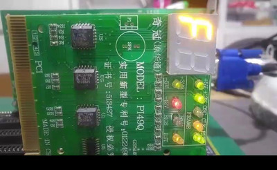
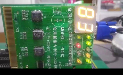
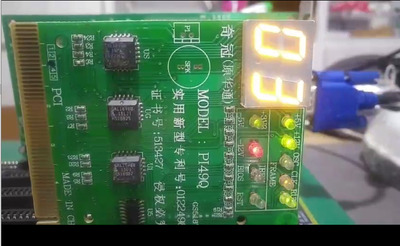
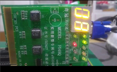
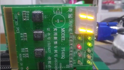
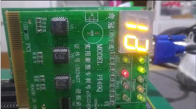
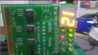
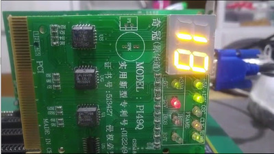
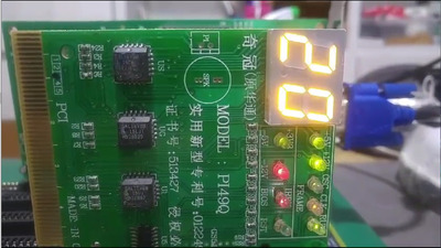
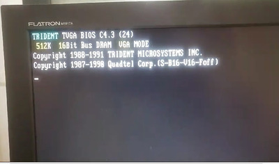
Here you have two videos with the startup sequence.
Sorry, apparently I cannot post videos. I will do some captures.
Here you have two videos with the startup sequence.
Sorry, apparently I cannot post videos. I will do some captures.
...............


.............
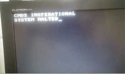
That's bad. Though perhaps not a hardware defect.
Could be that the CMOS contains spurious/false data due to loss of power.
A BIOS swap with another BIOS could help to correct this, to write meaningful data in to CMOS RAM.
PS: If you could somehow make the board to boot from floppy, at least..
CheckIt and other tools can test the motherboard components, Including the RTC.
"Time, it seems, doesn't flow. For some it's fast, for some it's slow.
In what to one race is no time at all, another race can rise and fall..." - The Minstrel
//My video channel//
I appreciate all your comments. Thank you very much.
I will think about.
Thank you.
Jo22 wrote on 2024-02-14, 08:47:That's bad. Though perhaps not a hardware defect. […]
That's bad. Though perhaps not a hardware defect.
Could be that the CMOS contains spurious/false data due to loss of power.
A BIOS swap with another BIOS could help to correct this, to write meaningful data in to CMOS RAM.
PS: If you could somehow make the board to boot from floppy, at least..
CheckIt and other tools can test the motherboard components, Including the RTC.
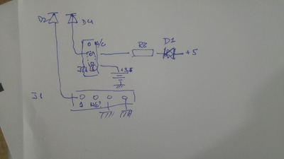
jnemo2004 wrote on 2024-02-14, 08:01:I have also to investigate how to set up properly the jumpers J1 and JP1
J1 is external battery connector - the outer pins should be GND and B+ (but never assume which is which, always check). I've seen some mobos that require a jumper to be installed on pins 2-3 for correct operation with external battery (or charging), so there might be some other uncommon settings as well. Especially on these older 286 mobos. Try to figure out where the middle pins go and measure voltage on the RTC/NVRAM chip. Make sure it is properly powered.
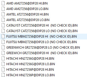
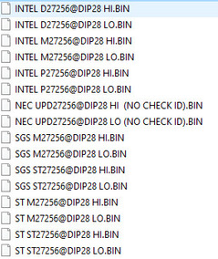
This is what I did:
- To read the BIOS chips (HI and LO) selecting all the brands for 27256 in my programmer and I compared the files contents to check if in any of them the reading was not the same (HI with HI and LO with LO).
All the files have the same content (HI with HI and LO with LO).
I cannot upload here two .BIN files (Hi & LO)
Regards
Jo22 wrote on 2024-02-14, 08:47:That's bad. Though perhaps not a hardware defect. […]
That's bad. Though perhaps not a hardware defect.
Could be that the CMOS contains spurious/false data due to loss of power.
A BIOS swap with another BIOS could help to correct this, to write meaningful data in to CMOS RAM.
PS: If you could somehow make the board to boot from floppy, at least..
CheckIt and other tools can test the motherboard components, Including the RTC.
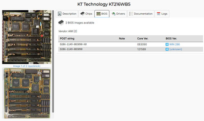
According to Murugan , the motherboard is like this:
https://theretroweb.com/motherboards/s/aquari … stems-ham-12-w2
And in this motherboar the jumpers are like in the attached picture.
Therefore, I will put the jumpers in the same position (in fact, actually, they are in such position)
Thank you.
Deunan wrote on 2024-02-14, 11:46:jnemo2004 wrote on 2024-02-14, 08:01:I have also to investigate how to set up properly the jumpers J1 and JP1
J1 is external battery connector - the outer pins should be GND and B+ (but never assume which is which, always check). I've seen some mobos that require a jumper to be installed on pins 2-3 for correct operation with external battery (or charging), so there might be some other uncommon settings as well. Especially on these older 286 mobos. Try to figure out where the middle pins go and measure voltage on the RTC/NVRAM chip. Make sure it is properly powered.
jnemo2004 wrote on 2024-02-14, 11:57:I cannot upload here two .BIN files (Hi & LO)
cant upload .bin files, zip them up
jnemo2004 wrote on 2024-02-14, 12:53:Therefore, I will put the jumpers in the same position (in fact, actually, they are in such position)
Eh, I wouldn't trust internet photos that much. It's a useful reference but not guaranteed to be correct. For example that particular photo already has the on-board battery removed, and I see a pretty wide trace going to JP1 middle pin. So good chances are this is related to battery power and could be already set for external battery - which is not connected on the photo.
The only sure way is to check where the pins of J1 and JP1 connect to.
Here, you have.
rasz_pl wrote on 2024-02-14, 13:02:jnemo2004 wrote on 2024-02-14, 11:57:I cannot upload here two .BIN files (Hi & LO)
cant upload .bin files, zip them up
I have already removed the battery socket and I have connected 3,6v Ni-Cd battery but nothing change.
I will try to find the right position of jumpers J1 and JP1 for internal battery
Thanks
Deunan wrote on 2024-02-14, 14:35:jnemo2004 wrote on 2024-02-14, 12:53:Therefore, I will put the jumpers in the same position (in fact, actually, they are in such position)
Eh, I wouldn't trust internet photos that much. It's a useful reference but not guaranteed to be correct. For example that particular photo already has the on-board battery removed, and I see a pretty wide trace going to JP1 middle pin. So good chances are this is related to battery power and could be already set for external battery - which is not connected on the photo.
The only sure way is to check where the pins of J1 and JP1 connect to.
jnemo2004 wrote on 2024-02-14, 15:17:I will try to find the right position of jumpers J1 and JP1 for internal battery
Just remember to test with a meter first, before you put a jumper on and apply power. Some of these pins will be GND or +5V directly and a jumper in the wrong place could cause a short and some damage.
In my opinion the jumpers are already set for the internal battery.
Thank you
Deunan wrote on 2024-02-14, 19:15:jnemo2004 wrote on 2024-02-14, 15:17:I will try to find the right position of jumpers J1 and JP1 for internal battery
Just remember to test with a meter first, before you put a jumper on and apply power. Some of these pins will be GND or +5V directly and a jumper in the wrong place could cause a short and some damage.
With motherboard ON, the voltage in 6818 +4,80v and with motherboard OFF the voltage is +3,47v (the rechargeable battery has 3,60v)
Deunan wrote on 2024-02-12, 20:49:CRxx32 is not going to power a good old 6818 for any reasonable amount of time. It's not even -A version. These mobos often used 6V external battery packs and even then would chew through them when unpowered for a long time. I'd strongly advise 3x or even 4x AA cell pack for this mobo. 3x might actually last longer because at 6V the power draw of the RTC/NVRAM chip actually increases quite a bit during seconds counting.
Anyway, as was already suggested the first thing to check is if the 6818 is getting powered properly from PSU. It might be able to keep NVRAM (and RTC) with the CR cell but not talk to the bus. And I also don't like the fact that one of the chips was messed with, do inspect the soldering. Could be the seller did a proper job of putting the chip back on the mobo but it's better to verify that.
The 6818 could be faulty. It's rare for this to happen in the mobo but if it was removed or swapped, who knows. As last resort I'd try to swap it (well actually I'd do it right away but then I do have spares on hand).
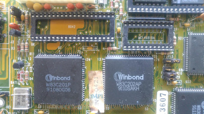
Someone left a wire or fiber on a resistor. After removing it I lost it and I can't tell if it was a wire or a fiber.
After removing it, the motherboard has the same behavior.
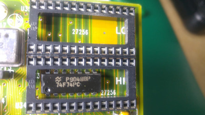
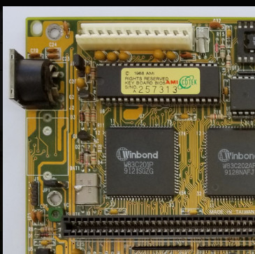
Under KBC motherboard looks ok.
jnemo2004 wrote on 2024-02-15, 07:01:Under KBC motherboard looks ok.
It does. Can you remove RTC chip and check under it as well? I think I see a bit of possible corrosion on that photo, between RTC and the big Winbond chip.
As for the jumpers, you are correct, the setting is for the internal rechargeable battery. J1 is for external battery with B+ on pin 1 and GND on pin 4. JP1 jumper is a bit of mystery, it looks like taking it off removes the on-board battery from circuit. Not sure for what purpose, it's not just to disable charging because it would also cut offline the power from RTC chip. So just leave it as-is I guess. It can be removed with external battery but if the mobo battery has been desoldered it makes no difference.
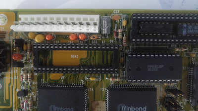
Here, you have it.
There was a little corrosion on one leg of D3 and R9. I remove the corrosion and it was only in the surface of the leg.
Under RTC , motherboard looks also OK.
My following steps in this next weekend is to remove all ICs in sockets , check them externally and put in all socket contact cleaner . Also I will do a test with the two BIOS dumps available in this motherboard:
In BIOS Even is equivalent to LO? and Odd to HI?
Thank you.
Deunan wrote on 2024-02-15, 11:17:jnemo2004 wrote on 2024-02-15, 07:01:Under KBC motherboard looks ok.
It does. Can you remove RTC chip and check under it as well? I think I see a bit of possible corrosion on that photo, between RTC and the big Winbond chip.
As for the jumpers, you are correct, the setting is for the internal rechargeable battery. J1 is for external battery with B+ on pin 1 and GND on pin 4. JP1 jumper is a bit of mystery, it looks like taking it off removes the on-board battery from circuit. Not sure for what purpose, it's not just to disable charging because it would also cut offline the power from RTC chip. So just leave it as-is I guess. It can be removed with external battery but if the mobo battery has been desoldered it makes no difference.