jnemo2004 wrote on 2024-03-03, 18:54:
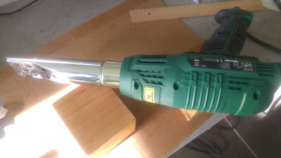
I have a hot air soldering station but not a professional one (could be enough for this job).
I will remove the chip but I have to practice before do it. I will protect the sorrounding components with ahesive silicon tape.
If I can offer some suggestions:
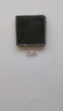
- Find a way to lift the chip up, this is usually done with suction tools but the professional ones are expensive and the cheap ones are not worth the money (they cause more problem than they solve). Perhaps a thin wire hooked under the corner pins would help you do that. You want to lift the chip up and not move it to sides, where it can "grab" a colder piece of solder pad and get stuck again, or even rip the pad.
- The chip should lift up with very little resistance. If you think a corner or a pin is still stuck then stop pulling and heat that spot. PLCC type pads don't rip off that easily but you don't know what kind of heat cycle was done to this mobo during previous desoldering, so the pads might now be weaker.
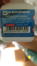
- Get some soldering flux for SMD work and put it around the chip pins. It will evaporate due to heat so have some fumes extractor or just open a window - but it's way easier with the flux, so don't be afraid to put too much. It can be cleaned afterwards with 90%+ IPA.
- This is a big PCB so depending on your hot air nozzle you might need to be very patient. For this job the bigger the nozzle, the better, but even with a small one you can just move it around to apply heat evenly.
- Try to pre-heat the mobo with a hair dryer from the bottom. Make sure it's hot, ideal target temperature would be 60-80C. Preheating will greatly reduce the PCB stress and desoldering time. On the other hand be careful if you want to apply bottom heating along with desoldering without temperature control, this can quickly create hot-spots so I would not recommend it. BTW even solder station with preheater will usually overshoot the temperature after cold power-on so don't put any PCB on cold preheater. Set it to 80-100% and let the temperature control kick in once or twice, then put the PCB on it.
If you have any kind of thermometer that can be used here - a thermocouple, or maybe IR sensor - do use it. Place it very close to the pads, preferably closer to the PCB center then to edge. It will be much easier to figure out how much heat still needs to be applied rather then guessing.