VOGONS


First post, by boby

User metadata
Rank Member
Rank
Member

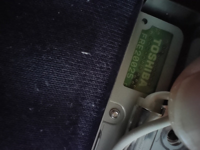
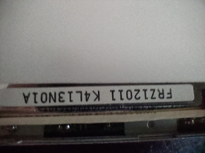
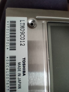
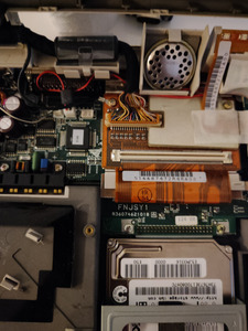
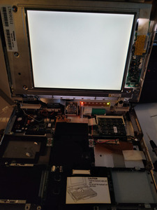
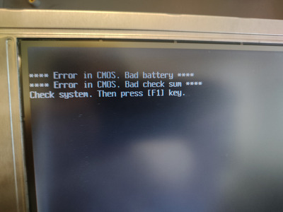
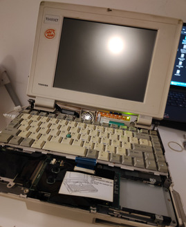
I have mentioned Toshiba which on power on shows only white screen. Laptop works, but the screen is white. If I connect it to external screen it works ok. Today I changed settings in bios to use less color and then after boot, I saw boot screen for one second and then it went white again.

This machine is 486 running on 75MHz (I think), 16 MB of RAM, 2 GB HDD. At the moment my floppy is not working (broken motor belt), so I can't install any system to see if some drivers might do the trick. I red this somewhere, but that makes no sense as the system graphic driver is not loaded on boot screen, so that probably won't help.

Any idea here, is it rather screen itself or some cable, as it showed image for one second?
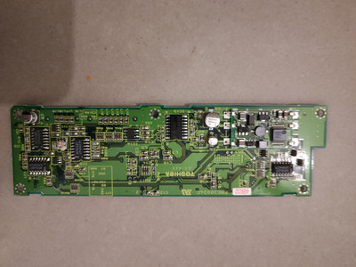
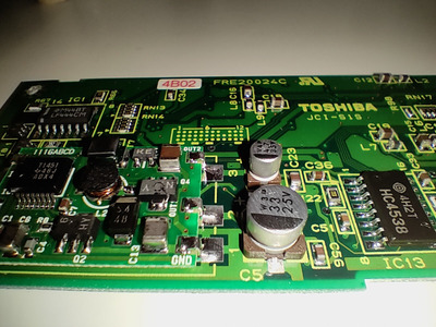
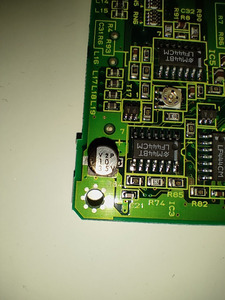
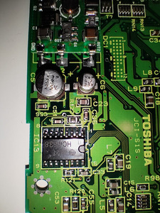
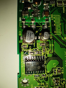
Attachments

Last edited by boby on 2024-03-01, 20:38. Edited 1 time in total.

Reply 1 of 27, by boby

User metadata
Rank Member
Rank
Member

Update: I checked all the cables and everything seams ok. I used multi meter to check if it beeps on both ends of the cables in the screen, but again, all good.
Used IPA to clean all the electronics inside but again all the same.

Any idea here what else to check?

Reply 2 of 27, by Thermalwrong

User metadata
Rank Oldbie
Rank
Oldbie

Thanks for confirming that it works when connected to the external monitor.

Can you take out the panel so we can see what panel it is? Typically in my experience a white screen means the LCD panel electronics are not functioning in some way - with Sharp screens of that era it's usually a connector between the main PCB that drives the rows and the PCB at the top that drives the columns. That could be something as simple as the connector being dislodged.
Alternatively, it could be bad capacitors in the LCD panel, those are not fun to replace but not impossible to do so.

A white screen wouldn't be a driver fault, the parts that run the LCD are much lower level. The C&T display controller sets up the LCD at the hardware level and drives it directly.

I've found that to get Toshiba LCD bezels off without damage, remove the screw cover stickers carefully since they tend to stay bent if they are pulled off at a sharp angle. I can't remember if there are screws under those rubber bits in the corners...
To remove the bezel, with one hand pull the bezel from where it opens for the LCD - while with the other hand use a plastic spudger tool to work along the edge where the bezel meets the housing. Once there's enough of an angle the clip for that area should pop off without taking a chunk of plastic off with it.
That even worked for the chalky glass-reinforced plastics of my Tecra 520CDT where I've broken plastic before. Your T2450CT has more robust plastic though

Reply 3 of 27, by boby

User metadata
Rank Member
Rank
Member

Thanks for detailed message. Not sure that I understood what to remove, but I already did remove the screen and took some pictures that might help.
Third image is the model of the LCD, I belive. Googled it and "new" one is around $400

Update 1: was able to dismatle the screen without damage, but took some time. There are screws under the stickers, you are right. 4 of them in each corner

Attachments

Reply 4 of 27, by Thermalwrong

User metadata
Rank Oldbie
Rank
Oldbie

If it worked for a second it's less likely to be a cable issue and more likely an internal connection in the LCD or a capacitor.
There's some good pictures of it here: https://ekososialismi.fi/brand_351405_extra/
Take out the LCD and remove these screws on the back to see the control PCB of the LCD. This is early in the days of active matrix so they're more complex looking than later more integrated LCD displays

ltm09c012-control-pcb.jpg
Filename
ltm09c012-control-pcb.jpg
File size
117.24 KiB
Views
485 views
File license
CC-BY-4.0

Look for SMD electrolytic capacitors with pads that are not shiny, or any brown / wet looking spots on the board which would be leaked & failed capacitors. Before replacement, you could try heating the area briefly with a hair dryer to see if that allows the LCD to start up.

You could also carefully try disconnecting the connections between the boards on the top and the one on the side - or even better, squeeze them while the laptop is on to see if it fixes the picture. Beware to avoid touching the wires of the CCFL, that would give you a shock.

Reply 5 of 27, by boby

User metadata
Rank Member
Rank
Member
Thermalwrong wrote on 2024-02-24, 19:49:
If it worked for a second it's less likely to be a cable issue and more likely an internal connection in the LCD or a capacitor. […]
Show full quote

If it worked for a second it's less likely to be a cable issue and more likely an internal connection in the LCD or a capacitor.
There's some good pictures of it here: https://ekososialismi.fi/brand_351405_extra/
Take out the LCD and remove these screws on the back to see the control PCB of the LCD. This is early in the days of active matrix so they're more complex looking than later more integrated LCD displays
ltm09c012-control-pcb.jpg

Look for SMD electrolytic capacitors with pads that are not shiny, or any brown / wet looking spots on the board which would be leaked & failed capacitors. Before replacement, you could try heating the area briefly with a hair dryer to see if that allows the LCD to start up.

You could also carefully try disconnecting the connections between the boards on the top and the one on the side - or even better, squeeze them while the laptop is on to see if it fixes the picture. Beware to avoid touching the wires of the CCFL, that would give you a shock.

I was checking that PCB earlier and it didn't look any suspicions. The only thing that did look somewhat different was one capacitor on the other PCB on the other side (visible after removing screen front bazel), Capacitor was somewhat "dirty" on the bottom (maybe acid), but I cleaned it with IPA and doesn't look broken. Not sure how to test it on my multimeter.

How to heat the area you mention, when the access is on the back of the panel?

Update 1: Here is the capacitor from the other PCB (the black one):

Attachments

  • IMG_4116.JPG
    Filename
    IMG_4116.JPG
    File size
    1.14 MiB
    Views
    465 views
    File license
    Public domain

Reply 6 of 27, by Thermalwrong

User metadata
Rank Oldbie
Rank
Oldbie

That appears to be the inverter which powers & runs the CCFL backlight - that component is working 100% because your screen is white.

You need to look at the innards of the LCD panel itself, the LTM09C012

Reply 7 of 27, by boby

User metadata
Rank Member
Rank
Member
Thermalwrong wrote on 2024-02-24, 21:36:

That appears to be the inverter which powers & runs the CCFL backlight - that component is working 100% because your screen is white.

You need to look at the innards of the LCD panel itself, the LTM09C012

Ok, but how to apply heat to the inner pcb, while the laptop is running? The pcb is on the back side of the panel. I need 3rd arm 🙂

Can I use heatgun, and should I use more then 100 degress (that is minimum)?

Reply 8 of 27, by Thermalwrong

User metadata
Rank Oldbie
Rank
Oldbie

That's a fair point. Personally I'm set up with a lot of tools like a generic inverter board that I can run from a 12v psu - when I'm testing LCDs in situ this generic inverter lets me move the lcd panel away from the housing for testing.

Putting too much heat on the laptop can be bad - I have melted keyboard keys thinking a hair dryer would do no harm. 100C on a small spot or a hair dryer aimed away from the keyboard should work.

Hmm, take a look first of all rather than testing stuff while it's running.

Reply 9 of 27, by boby

User metadata
Rank Member
Rank
Member
Thermalwrong wrote on 2024-02-24, 22:01:

That's a fair point. Personally I'm set up with a lot of tools like a generic inverter board that I can run from a 12v psu - when I'm testing LCDs in situ this generic inverter lets me move the lcd panel away from the housing for testing.

Putting too much heat on the laptop can be bad - I have melted keyboard keys thinking a hair dryer would do no harm. 100C on a small spot or a hair dryer aimed away from the keyboard should work.

Hmm, take a look first of all rather than testing stuff while it's running.

Here is the PCB - doesn't look like anything is broken on it:

Attachments

Reply 10 of 27, by Thermalwrong

User metadata
Rank Oldbie
Rank
Oldbie

Thank you 😀 It's neat that the whole control PCB can come out - beware of those little adjustable resistor / trim-pots, those are factory calibrated and should not be changed. Getting them back to proper values is tough if they get changed and I don't know how to do that other than comparing with a known good board.
The electrolytic caps are the wear part on these boards and you can see how they caused a failure with silvestron's video on the T4400C - very similar LCD panel! https://youtu.be/Of6y084KvTY?t=1411

The negative side of C5 looks discoloured, as does C6. Looks like the other electrolytic is C1 and that looks okay from your picture but replacing all 3 of the electrolytic caps may help. At least you could remove them (ideally with a soldering iron rather than with hot air) and use a transistor tester to check the health of the caps. If you don't have one, touching each of the pads of the electrolytic capacitor with the soldering iron to see if it sizzles / makes a fishy smell is a great test of whether they've leaked electrolyte or not.

On the other side of the PCB, check that the F1 fuse has 0 ohms across it, maybe that blew somehow.

Reply 11 of 27, by boby

User metadata
Rank Member
Rank
Member
Thermalwrong wrote on 2024-02-24, 22:30:
Thank you :) It's neat that the whole control PCB can come out - beware of those little adjustable resistor / trim-pots, those a […]
Show full quote

Thank you 😀 It's neat that the whole control PCB can come out - beware of those little adjustable resistor / trim-pots, those are factory calibrated and should not be changed. Getting them back to proper values is tough if they get changed and I don't know how to do that other than comparing with a known good board.
The electrolytic caps are the wear part on these boards and you can see how they caused a failure with silvestron's video on the T4400C - very similar LCD panel! https://youtu.be/Of6y084KvTY?t=1411

The negative side of C5 looks discoloured, as does C6. Looks like the other electrolytic is C1 and that looks okay from your picture but replacing all 3 of the electrolytic caps may help. At least you could remove them (ideally with a soldering iron rather than with hot air) and use a transistor tester to check the health of the caps. If you don't have one, touching each of the pads of the electrolytic capacitor with the soldering iron to see if it sizzles / makes a fishy smell is a great test of whether they've leaked electrolyte or not.

On the other side of the PCB, check that the F1 fuse has 0 ohms across it, maybe that blew somehow.

F1 shows 0.8 ohms.
If I do this test with iron on both side of caps, I should use flux too, right? Because, flux smell can mask the other "smels", I think.
Or, you mean just a quick test without flux, to check the sound/smell, because electrolyte will cause it?

Reply 12 of 27, by Thermalwrong

User metadata
Rank Oldbie
Rank
Oldbie

Nah try without flux first, if there's electrolyte on the capacitor leg it'll boil / vaporise. It looks like there's no flux already there which is what I expect for factory original electronics like that, if it's a good capacitor then there's no electrolyte then it should make no particular sizzling or smell.

Reply 13 of 27, by boby

User metadata
Rank Member
Rank
Member

There are some traces of acid like on the caps legs. I cleaned it with IPA and I was planning to heat it a bit and try then.
In case I need to replace them, where can I buy some?
Also, they are surface soldered, so might be a bit too hard for me 🙂

Reply 15 of 27, by Thermalwrong

User metadata
Rank Oldbie
Rank
Oldbie

That's great news 😀

Personally I'd go with MLCC capacitors since the technology has moved on since this board was manufactured and higher capacitance MLCCs are available now. Also you can get MLCC capacitors that are big enough to fit on the pads.

Can you measure the diameter of each of the capacitors and I could then recommend some easily available MLCC capacitors to fit in their place?

You can probably get away with just replacing C6 to start, now I look at it more it looks terrible. But replacing all 3 would be best in the long run

Reply 16 of 27, by boby

User metadata
Rank Member
Rank
Member
Thermalwrong wrote on 2024-02-26, 12:41:
That's great news :) […]
Show full quote

That's great news 😀

Personally I'd go with MLCC capacitors since the technology has moved on since this board was manufactured and higher capacitance MLCCs are available now. Also you can get MLCC capacitors that are big enough to fit on the pads.

Can you measure the diameter of each of the capacitors and I could then recommend some easily available MLCC capacitors to fit in their place?

You can probably get away with just replacing C6 to start, now I look at it more it looks terrible. But replacing all 3 would be best in the long run

C1, diameter around 5mm, height also around 5mm -> 35 V
C5, diameter around 6mm, height around 5mm -> 25 V

C6, diameter around 4mm, height 5mm -> 35 V

Can't be 100% sure as there are these mounting plastics around, but that should be aproxx messure.

Attachments