Reply 20 of 27, by Thermalwrong
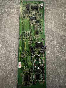
There is a height limitation for the capacitors because it's inside the screen housing. Max height is 5mm and that means you'd have to carefully arrange any electrolytic capacitor on its side like silvestron did in his video.
Personally I'd go with MLCC capacitors because they're tiny and they're non polarised so they can't be installed backwards. They also won't leak (like electrolytic caps), explode (yellow tantalums) or be too expensive (polymer tantalums).
Here are my recommendations for surface mount capacitors which are less work to arrange in the casing:
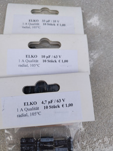
C6 - search on ebay for "High Quality 1206 SMD/SMT Capacitors. ALL VALUES. 25pc. UK Seller. Fast Dispatch" they have an option for "4.7uF / 50V / X5R". That should work and fit nicely in the C6 footprint
C5 - ebay "10pcs 6.3V to 5KV 1812 SMD/SMT Capacitors Range 100PF 680PF 1NF 68NF to 100uF" value: "25V 33UF +-10% X7R"
C1 - ebay same as C5 but value "35V 10UF +-10% X7R"