First post, by dura-zell
Hi
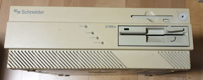
Currently on my bench sits a "Schneider D486 20"
As the name implies, its an 486. Specifically an 486-SX, clocked at 20MHz. The whole thing is a bit weird as there are almost no infos on this machine on the web. (No, its not an CPC type machine and not something in the line of the "Euro AT", both of which were built by Schneider). I'll put some pictures at the end of the post.
Unfortunately - before I can try out the computer, I need to fix the PSU. And this is where I need help. I wasn't able to find any schematics and reverse engineering an SMPS is a bit over my head. The PSU itself is a bit weird as it is neither a regular AT PSU nor an ATX type of PSU but something in between. The power connector itself is also something specific to this machine.
Symptoms:
Whe power is applied and the device is powered on, I get no power whatsoever on the power connector or on the two Molex connectors.
Here is what I know:
- the PSU is built by a company called "dual" and was OEMed by Schneider for this specific line of computers
- The PSU is a switch mode power supply on one side but has a linear power supply also built in
- the linear part has the sole purpose of operating a relay which in turn controls the pass-through connector for a screen and power to the switch-mode part of the PSU
- the machine is powered by turning a key in the front of the device. This is routed to a connector on the mainboard and from there to a pin on the main power connector.
- The SMPS part of the supply seems pretty standard but uses a somewhat unusual / rare controller chip ( SGS-THOMSON TEA2260)
Here is what I did so far
- visual inspection and cleaning: Looks good so far, no cold solderjoints, no leakage. Lots of flux on the underside but this looked like fabrication residue and not someone trying to fix it. Cleaned that up.
- the linear part is working fine. Switch works, relay works and the SMPS part gets power as expected
- fuse is fine
- measured all caps out of circuit. Changed most of them, even when there were within specs just to make sure.
- checked all diodes
- checked all recitifiers
- checked the high voltage side: Power gets to the HV rectifier, to the controller chip and to the power transistor (Sharp S2000A)
- checked said transistor out of circuit with a testing device and additionally with a diode tester
- measured the low voltage side: directly after the transformer for the low power side, there is already now voltage
What I did not so far:
- checking the optocoupler. I have no idea how to check this
- testing the pulses from the controller chip to the transistor: I have a scope but dont want to risk frying it as there is high voltage in play and this part of the PCB is pretty cramped. I measured these with the multimeter, there is some voltage but I can't tell if it is correct.
I know that I can swap in a regular ATX PSU but I want to keep the original one if possible as it is quite an oddball which deserves to be preseverd (at least in my opinion).
So after this "wall of thext" now my question(s):
Has anyone heard of this computer in general and can supply any info about it. Obviously I'm particular interested in the PSU but as there is literally no info at all in the web I would take anything else gladly.
If there were any schematics of the PSU I would be extremely happy.
Has anyone an idea about where to look, what to check - any hint would be appreciated.
As for my background: I know how to work with electronics and also with line-voltage. I can read schematics and operate testing equipment and I'm aware of the risks involved here (charged caps, high voltage DC etc.)
Front of the computer:
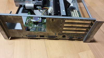
Back of the computer:
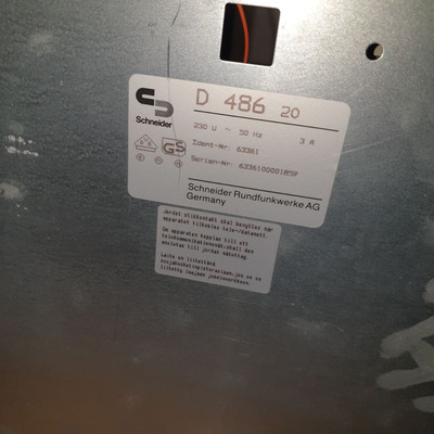
Bottom with model/serial:
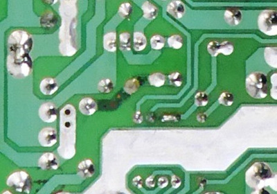
PSU top and bottom view:
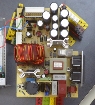
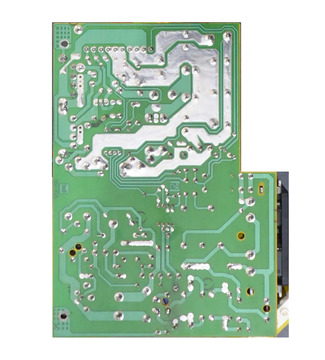
Please note that the bottom is flipped to match the top side. Tried to follow the traces here. Please also note that there are two daugher boards involved. Both are sticking vertically out of the main PCB and are therefore not good to see.
One is located near the large cap on the high voltage side of the PCB and holds the controller chip and some passives. The other one is just below the mainboard connector and has an analog comparator on it. I assume it is part of the regulation circuit and/or generates a power good signal. I'm not allowed to add more than 5 pictures to this post but will supply additional pictures if needed.
Greetings,
dura-zell