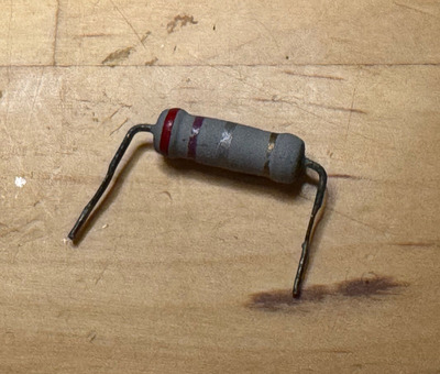
ubiq wrote on 2024-03-02, 05:25:My multimeter probes shorted give 0.2 ohms. I put that resistor back, but in-circuit it's reading 0.6 ohms.
OK, I think we can give that a pass for now.
Techincally, 0.2 Ohms from MM probes + 0.27 Ohms from the resistor should give about 0.5 Ohms... but at these low resistances, it's acceptable for the MM to show error like this.
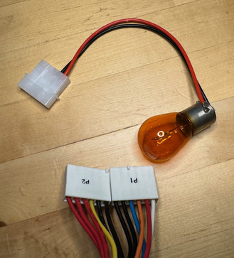
ubiq wrote on 2024-03-02, 05:25:I didn't have anything around the house, so I picked up a couple auto light bulbs as suggested - 12V, 21W each. Hooked one up to the 5V rail (one should be good right?) and it didn't change anything.
So you still got about 1.2V out on the 12V rail and 0.5V on the 5V even with that, or were these readings even lower?
ubiq wrote on 2024-03-02, 05:25:Btw, this PSU uses non-standard coloured wires, but I figured it out.
Ah OK, thanks for noting that.
Looks like PG (Power Good) is white instead of orange, 12V rail is orange instead of yellow, and -5V is yellow instead of white.
ubiq wrote on 2024-03-02, 05:25:I tried to check the resistances on all the rails, but the only one I could get a good reading on was the -12V at 2.1 KΩ. The others would always give different readings and wouldn't settle, always climbing or falling, never consistently. Sometimes 15MΩ and falling, sometimes 4KΩ and rising, etc. Seemingly random.
That's fine for now.
High resistances are OK, especially any climbing ones (it's the output caps charging.)
I was just looking to see if there are any low-resistances, particularly sub-30 Ohms, to check if there are any suspicious / potentially bad output rectifiers. That said, a good number of older PSUs - and especially cheaper ones - have low-resistance resistors on some or all of their output rails as "dummy" loads (to provide a minimum starting load for the PSU if there isn't one provided by the motherboard/hardware.) Just mentioning this, since a low resistance on the output doesn't always mean something is shorted. But if there is low resistance and there aren't low resistance resistors, that's when it's worth further investigating.
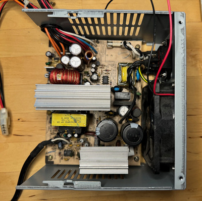
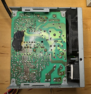
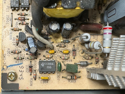
ubiq wrote on 2024-03-02, 05:25:Here's that better close up you wanted:
Awesome, thank you, that really helps.
So it looks like the PWM IC is a KA3884... which is a pretty close cousin to UC384x series (actually, it might even be a pin-compatible / drop-in replacement.)
And what I find very interesting from this picture is that the PSU doesn't have a switch for the mains like most AT PSUs do. Instead, the switch appears to be connected to the VCC pin (pin #7) of the PWM IC, thus only enabling the IC when it is turned On. The switch appears to have black and white wires and connects to the board where it says "SW1".
With that said, use your multimeter and measure the resistance of the switch when it is in the Off position and also when it is On. In particular, it's the On resistance that's of interest here. You should get a nice low resistance, preferably under a few Ohms. Make sure the PSU is UNPLUGGED FROM THE WALL and the two big capacitors discharged (less than a few Volts across each) before touching anything with your multimeter.
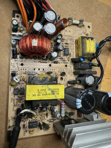
While you have the PSU unplugged, also check the resistance of resistor R102. It appears to be a 270 KOhm resistor(?) It's located right in front of the leftmost big 200V capacitor shown in your top-side picture above. Also check the resistance of Zener diode ZD302 and report what resistance you get. It's close to R102 and the big 200V cap as well.
Also, while I don't think a "bouncy" switch should have any effect on the operation of the PWM IC, it still may be worth to perform the following test:
Put the switch in the ON position and then plug in the PSU to see if that changes anything with the PSU being able to turn On or not.
If not, do the the following test next: unplug PSU and have your multimeter set to measure the DC voltage between *primary* side ground and the white wire on the PSU switch that goes to the front of the case. Again, CAUTION white taking this measurement as to not touch any metal part of the MM probe, since this is the primary side (not isolated, hence shock hazard.) Primary ground is the negative (-) lead of the leftmost big 200V capacitor of the top-side picture you provided above (re-linking below for convenience):
download/file.php?id=186754&mode=view
With multimeter set and ready, plug in the PSU (or more conveniently, have it connected to a power strip with a switch) and note the voltage read by the multimeter. Report back what you get. The KA3884 IC needs at least 16V DC on its VCC pin to start switching. Since the white wire of the switch connects to the VCC pin, this will tell us if the PWM IC is getting proper VCC or not.
ubiq wrote on 2024-03-02, 05:25:Oh, and I have LCR and ESR meters, if they would be any use here.
YES, those would actually be super useful!
I honestly wasn't expecting you to say you have such equipment.
Since you do, desolder and check the small capacitors near the KA3884 IC out of circuit. These are related to the startup and run function of the PWM IC, so a bad cap there can easily make the PSU not want to start (and in fact is a common failure on small power adapters, such as ones for routers and chargers.)
Last but not least, I see some tan glue. Just see if there is any of this glue anywhere on the PSU where it has turned brown or dark brown. This glue is known to go conductive when it does this. It was commonly used by many manufacturers back then.
I think that's about enough homework for you now. 😀 Hopefully it isn't too much and feel free to ask for more details if you need any.