kotel wrote on 2024-03-01, 19:56:
Hi
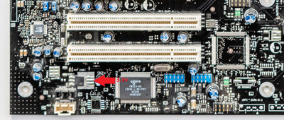
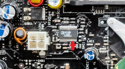
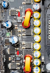
I recently got an intel D865PERL motherboard. After power is restored it imminently turns on. Post card shows that cpu is stuck in reset and no post codes. There are also 2 bulging 560μF 6.3v caps, but i don't have any replacements on hand (closest i got is 680μF 10v). Tried diffrent cpu, psu's. Replaced CMOS battery but still nothing. Also cpu isn't getting warm, but the north bridge is. Any ideas what to try next?
ive had this issue with a couple of boards, i wouldnt have thought 2 buldging caps would prevent the board from working , i had an msi board with eleven 6.3v 1000uf caps, all buldging or leaking and the board still worked fine, tho caps can fail even if they look good so you can never be sure, those caps you have are close so i would try them out but i wouldnt run the board for long with them in. i think your problem is the bios, either a bad flash or its just corrupted for no reason which can happen. ive got a gigabyte board that does it every so often, ill plug it in and it turns itself on to a blank screen, it has dual bios probably for that reason, eventually i manage to get it to boot from the backup bios, then i reflash the bios. i've had other board do the same and its usually bios related, try a reflash or a new bios chip.