VOGONS


First post, by cendof

User metadata
Rank Newbie
Rank
Newbie

Hi, my power supply died suddenly on Fujitsu DL900 matrix printer. Does anybody have info regarding DC voltage to motors? 5v DC is clear to me for logic, but for motors should be more than 24 V DC. I hope 😀 Does anybody have schematics maybe? It is from 1992.

Why I am asking?! I did complete restoration of this printer, but died at 1st test after restoration.

Reply 1 of 10, by momaka

User metadata
Rank Member
Rank
Member

I'm no good when it comes to finding schematics. However, gonna post here here in case this turns into a PSU troubleshooting discussion, since I do have experience repairing SMPSes.
Indeed on more modern printers (>2000's), 24V is what is used for motors (some inkjet HP's even use 32V adapters... though I suspect that voltage is buck-regulated down to a lower voltage.) So 5V for logic and 24V for motors sounds reasonable. Would have to see a top and bottom picture of the power supply's PCB to tell you more accurately if that's the case or not, though.

Reply 2 of 10, by cendof

User metadata
Rank Newbie
Rank
Newbie

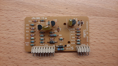
Hello, sorry I am not at home, vaccation, I have only top picture.

20240211_101433.jpg
Filename
20240211_101433.jpg
File size
1.05 MiB
Views
288 views
File license
Public domain

Anybody owning this printer, DL700, DL1100 also good.

Reply 4 of 10, by momaka

User metadata
Rank Member
Rank
Member

OK, I did a search for a "Fujitsu DL1200 power supply" on ebay, and indeed the outputs are 34V and 5V.
In particular, this is the order of the output pins from bottom to top when using the picture you posted as a reference and information found from eBay listing:
+34V, SG2, SG1, 5V, PW/ST
I'm not 100% sure what SG2 and SG1 are, but I imagine probably Secondary Ground 2 and Secondary Ground 1. Not sure if they are tied together, though - this I would need a bottom-side picture to trace or you would have to check with a multimeter (when you get back home... hope you have a good vacation for now. 😀 )
And the last pin, PW/ST... that might be some kind of power-on signal or a signal pin to wake up from a low(er) power mode and normal operation. There is only one transformer, so the 5V power supply should be On as soon as the PSU is plugged into the wall.

But before further diving into troubleshooting the PSU, indeed try supplying 5V and 34V to the printer to see if it works. Just observe that you wire all of the power rails and ground correctly. I imagine that even without the 34V rail, the printer should still at least appear as "ready" when connected to the computer, since 5V would be for the logic circuits, which should be able to communicate with the PC. If that doesn't work, perhaps there may be something else going on with the printer? Let us know what you find when you get back / have more time to check the items above.

Reply 5 of 10, by cendof

User metadata
Rank Newbie
Rank
Newbie

Hello,

I am attaching also bottom side pic, transformer is currently out; it seems strange as I can not measure continuity on primary (3 pins) and secondary side. More I will know during this week.

Tnx for all suggestions.

Attachments

Reply 6 of 10, by momaka

User metadata
Rank Member
Rank
Member

OK, using the above photo as a reference, the left-side column of pins is the primary side of the transformer. First and 2nd pin from the top are for the primary main winding. On the transformer itself, these two pins should measure pretty low resistance to each other and no resistance / continuity to any other pins. The 3rd, 4th, and 5th pin (last pin on bottom) are for the primary auxiliary winding and/or feedback winding. These three should show low resistance / continuity to each other when measuring the transformer, and no resistance / continuity to any other pins.

As for the column of pins on the right side - that's the secondary side. All of the pins, except possibly the last one on the bottom, should show continuity to each other.
Doing some tracing, I believe the output rail pinout I suggested in my previous post is correct. So it's indeed 34V, Ground, Ground, 5V(?), and Activate/PS_ON(?)

By the way, be careful when handling the board, especially with the transformer removed - that large electrolytic cap on the primary could possibly remain charged up for a long time if there is no discharge path for it on the PCB. Depending on which part of the world you live it (i.e. country with 230V AC or 120V AC), the cap could have either up to 340V DC or 170V DC on its terminals. Discharge before doing any resistance measurements on the primary side of the PSU - both for your own and the safety of the multimeter. 😀
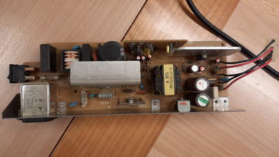
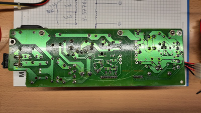
Reply 7 of 10, by cendof

User metadata
Rank Newbie
Rank
Newbie

I am still alive, but without any good news. I checked all elements on the smaller PCB and all are good. Transformers seems also good, but how to check if oscillator starts? I checked with multimeter what is going on on the gate of the mosfet, some DC voltage is there, but I can't use oscilloscope as I don't have it. The only thing that is good, nothing is blowing up and also the main capacitor is charging. On the PCB there are some diodes, but all are so burned out that nothing can be seen on them, also the direction mark (line) is not visible anymore. Checking them with diode tester did not show any fault, resistors also seem ok. Can somebody suggest which part is the oscillator? I really don't have any other idea, so any suggestions would be welcome.

Attachments