VOGONS


First post, by kotel

User metadata
Rank Newbie
Rank
Newbie

Hi

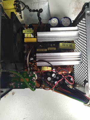
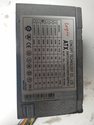
I recently wanted to give a shot at reparing this Logic LC-B300ATX. There are some burnt 12v cables and an resistor connecting 5v to ground (which i think is a load resistor) has crumbled. After applying power, 5Vsb goes to 9v then slowly starts dropping down. Shorting PS_ON with ground does nothing. I've found a schematic for the ATX 2005 chip, but don't know where to go next. Any help would be appreciated.

Attachments

Reply 1 of 14, by dominusprog

User metadata
Rank Member
Rank
Member

Have you changed the mosfets? If not, changing them would be a good start.

Duke_2600.png
A-Trend ATC-1020 V1.1 ❇ Cyrix 6x86 150+ @ 120MHz ❇ 32MiB EDO RAM (8MiBx4) ❇ A-Trend S3 Trio64V2 2MiB
Aztech Pro16 II-3D PnP ❇ 8.4GiB Quantum Fireball ❇ Win95 OSR2 Plus!

Reply 2 of 14, by momaka

User metadata
Rank Member
Rank
Member

That's a Deer / Solytech power supply. The "LC" series are pretty much the lowest end units... though yours actually looks much better built than the others. Anyways, I'll continue on this point later below.

Now for the high 5VSB...
WARNING: DO NOT CONNECT THIS POWER SUPPLY TO A MOTHERBOARD YET / WITHOUT CORRECTING THIS ISSUE.
Such high 5VSB = instant motherboard death, usually (typically the SIO / LPC bites the dust.)

What's the cause of the 5VSB going so high?
- Solytech used an old (almost ancient) design for the 5VSB circuit, known as 2-transistor self-oscillator. It has no PWM control ICs, and therefore such circuits usually have NO PROTECTION against... almost anything (including over-voltage.) That's not to say these circuits are bad. However, many of them often use a design with a "critical" startup cap, which when it fails, can make the 5VSB go very very high. The cap in question can be found close to the "EEL-19-2005" small transformer and primary heatsink. If I'm not mistaken, this cap is rated either 50V 22 uF or 50V 47 uF.

Not only that, but if the output caps on the 5VSB circuit (typically 2x 10V 1000 uF) fail, this can also cause the 5VSB to oscillate wildly and produce higher-than-normal voltages.

So the SOLUTION is: replace all of the above mentioned capacitors associated with the 5VSB circuit. For the 2x 1000 uF caps (or they might be 680 or 820 uF, depending oh how cheaply or not your PSU was built), you could also use 2x 1200 or 1500 or 2200 uF. It's the 5VSB circuit, so it doesn't care much. Just make sure to use good quality Japanese low-ESR caps.

By the way, this 5VSB design is what gave Bestec power supplies (and eMachines) a bad name. In the case of Bestec power supplies, actually only the ATX-250-12E model was responsible for this bad reputation. The ATX-250-12Z model uses a PWM-FET IC for the 5VSB and it's completely safe.

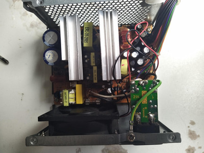
In regards to the rest of this LC-B300ATX power supply: it's not a completely gutless unit. Given the right parts, it should make for a decent 200-250 Watt power supply. The numbers on the label, of course, are a complete lie. I can't see the size of the rectifies attached on the secondary side heatsink, but from what I have seen in many of these units, typically the 5V will have a 20 or 25 or 30 Amp rectifier, 3.3V a 16 or 20 Amp rectifier, and 12V either a 10 or 12 or 16 Amp rectifier if you are very lucky. So depending on what your PSU has, that's what's going to be the max current for each rail.
Now, on the plus side, the input filtering is already there and Solytech did install proper Y2 and X2 safety EMI/RFI suppressing caps. The main transformer looks to be of proper 35 mm width, which is typically good for up to 300-350 Watt designs (at least for older half-bridge topologies like this.) And finally, it's good to see that each output rail (3.3V, 5V, and 12V) have 2 filter electrolytic caps and PI coils. The cheaper LC PSUs usually omit the PI coils and may have only 1 cap per output rail (or they will only have 2x 1000 uF caps instead of 2200 uF caps). That said, post a picture of the underside of the PSU. Some ultra-cheap LC designs bypassed the PI coils with traces. With the LC line, you never know what you are going to get until you open it and inspect it carefully. But again, once rebuilt, they do make for decent PSUs. I have a Deer DR-250ATX that's almost the same thing as the LC line. It's been powering a Pentium III PC for 15 years now. Of course I had it fully recapped it when I got it (it was a freebie unit and dead, due to... *sigh*... bad caps.) It was my 2nd or 3rd PSU recap back in the late 2000's and still works great to this day.

That said, try replacing the caps mentioned above and see if the 5VSB goes back to normal operation. Then see if the power supply will turn on when you jumper PS-ON to ground. If not, it's possible that either the PWM chip or the BJT driver circuit got damaged from the over-voltage, since these are also supplied by the 5VSB supply (actually, they are supplied by their own auxiliary power rail, but this rail is also derived from the 5VSB transformer, so that's why the damage can be a little more widespread.)

In any case, these PSUs are pretty easy to fix and don't require any special unobtanium parts. The "2005" PWM IC might be the hardest one to find (if it has been damaged). Otherwise, the rest is all "jellybean" parts that anyone sells.

dominusprog wrote on 2024-03-21, 08:15:

Have you changed the mosfets? If not, changing them would be a good start.

There's going to be exactly 1 MOSFET in this PSU, and it will be for the 5VSB, on the primary heatsink. The fact that the 5VSB is outputting power, though, means that this MOSFET is OK.
The other two parts on the primary heatsink are going to be 2x E13007 or equivalent NPN BJTs. It's an ancient half-bridge design that Solytech and many many PSUs used for a lot of years - some as late as the mid-late 2000's. Gutless no-name PSUs also still use this design, since it's well understood and relatively cheap to build and modify.
Reply 3 of 14, by kotel

User metadata
Rank Newbie
Rank
Newbie
momaka wrote on 2024-03-21, 13:33:

So the SOLUTION is: replace all of the above mentioned capacitors associated with the 5VSB circuit. For the 2x 1000 uF caps (or they might be 680 or 820 uF, depending oh how cheaply or not your PSU was built), you could also use 2x 1200 or 1500 or 2200 uF. It's the 5VSB circuit, so it doesn't care much. Just make sure to use good quality Japanese low-ESR caps.

Replaced those caps and the 5Vsb went down to 5.03v, which is good. Sadly, it doesn't wanna start. After i apply power, i hear some strange shorting/buzzing sound for a few seconds. Any ideas?

Reply 4 of 14, by momaka

User metadata
Rank Member
Rank
Member

There's going to be a small 50V 47 uF (IIRC) cap on the secondary, near the 5VSB transformer (the "EEL-19-2005" one). Make sure that one is good too. That's the secondary side aux. rail that supplies power to the 2005 PWM IC as well as the BJT driver circuit. If that checks out, check all of the small components near the "EEL-16-2005" transformer (i.e. the BJT drive transformer), both on the primary and secondary side. On the secondary side, there's going to be two small transistors - typically they are TO-92 or TO-92L case size and likely have a part number c945, 2n2222a, or similar. Pull these out and check them as well. Also check any diodes in that area. On the primary side, there's going to be 2-4 low-value resistors, 2-4 small diodes, and 2 med. value resistors (typically 2.7 KOhm). These are for the BJT drivers. Check these as well.
Finally, look for any burned/overheated resistors near the 5VSB transformer and near the 2005 PWM chip. Any such burned resistors should be pulled and checked for correct resistance. If there is a small resistor that is very burned up near the 2005 PWM chip, there's a good chance the PWM chip could be bad.

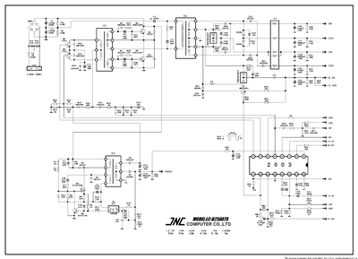
Attaching a schematic of an LC-B250ATX. It may not be the exact same thing as your PSU (and uses Solytech's custom "2003" chip instead of their newer "2005") but it should be very very similar.

On the schematic, transformer T1 corresponds to the big main transformer in your PSU, T2 is the middle BJT driver (the "EEL-16-2005"), and T3 is the 5VSB transformer. They may not have the same designator numbers PCB, but that's why I'm giving you their location in your PSU and the schematic. From this, hopefully can see which of the components I talked about above. In particular, check the components that appear with the following designators on the schematic (and remember, these might have different designator numbers on the PCB of your PSU, or they may not.):
resistors: R29, R33, R34, R37, R24, R36, R10, R11, R13, R18
diodes: D12, D16, D19, D10, D4, D6
small transistors: Q5, Q6

For the resistors, check any for open or abnormally-high resistance.
For the diodes, it may be a bit tricky to do without removing them from the board... but if you get any low diode readings under 500-700 mV on your multimeter, remove and check out of circuit. Same goes for transistors Q5 and Q6. Also, if resistors R10, R11, R13, or R18 are blown (unlikely), you might have to remove the two BJTs on the primary heatsink (labeled as Q1 and Q2 in the schematic.)

Attachments

Reply 6 of 14, by kotel

User metadata
Rank Newbie
Rank
Newbie

Finally got back to repairing this psu. Diodes all have above 500 mV. The two small transistors are also ok. There are 2 resistors near the 2005 chip,R48 and R50 that are like blue-greenish color ( R48 is more green than R50). Ist it normal? I've also noticed that PG cable has de-attached itself from the board. Ill solder it back on and check the rest of components.

Reply 7 of 14, by PcBytes

User metadata
Rank Oldbie
Rank
Oldbie

Replace ALL lytic caps in the 5vsb section (even the small ones). I had a CWT ISO with this overvolted 5vsb issue and it went away after I replaced every little bugger in the 5vsb circuit.

"Enter at your own peril, past the bolted door..."
Main PC: i5 3470, GB B75M-D3H, 16GB RAM, 2x1TB
98SE : P3 650, Soyo SY-6BA+IV, 384MB RAM, 80GB

Reply 8 of 14, by kotel

User metadata
Rank Newbie
Rank
Newbie
PcBytes wrote on 2024-04-12, 11:59:

Replace ALL lytic caps in the 5vsb section (even the small ones). I had a CWT ISO with this overvolted 5vsb issue and it went away after I replaced every little bugger in the 5vsb circuit.

But I fixed the 5vsb overvoltage issue. Now it just doesn't wanna start. Not sure how 5vsb line is relevant to psu not starting. Also, should I replace that 5v load resistor?

Reply 9 of 14, by PcBytes

User metadata
Rank Oldbie
Rank
Oldbie

Whoops, missed that...

Assuming you have 5vSB, check if any of the secondary rectifiers are shorted.
I've had similar LC units that would show 5vSB but not start and their issues were one of the secondary side rectifiers being dead (usually 12v, but 5v and 3.3v can go bad too).

"Enter at your own peril, past the bolted door..."
Main PC: i5 3470, GB B75M-D3H, 16GB RAM, 2x1TB
98SE : P3 650, Soyo SY-6BA+IV, 384MB RAM, 80GB

Reply 10 of 14, by momaka

User metadata
Rank Member
Rank
Member
kotel wrote on 2024-04-11, 11:02:

Finally got back to repairing this psu. Diodes all have above 500 mV. The two small transistors are also ok.

If you checked those in-circuit, pull them out and re-check them out of circuit for proper Vbe and Vbc voltage drops on your meter (and if your meter has hFE function test, see if they show OK on that too.) Reason I suggest this is because the small transistos are notorious for going open-circuit between junctions when overloaded.
All diodes reading above 500 mV is a pretty good sign, but make sure none read too high over 700 mV either as that can be an indication of an open-circuited diode (which is rather rare for diodes, but not impossible.)

kotel wrote on 2024-04-11, 11:02:

There are 2 resistors near the 2005 chip,R48 and R50 that are like blue-greenish color ( R48 is more green than R50). Ist it normal?

I can't see them on the picture, so I can't tell. But do the color bands on them look darker than normal? Also, is the PCB underneath or near these resistors darkened / burned? If yes, they might be bad ---> in which case, remove from the board and check for proper resistance. Otherwise, it's just color variation from the factory (and as to why only these two are green/blue, you'd probably have to ask a bean counter on the production floor at Solytech when these PSUs were made - probably no one else knows why.)

kotel wrote on 2024-04-12, 16:57:

Not sure how 5vsb line is relevant to psu not starting.

If the 5VSB line over-volts, there's always a chance either the PWM controller could be taken out or the drive circuit for the BJT drive could get damaged.
Most of the time, the PWM controller survives, since many TL494/KA7500 and similar clones are capable of handling up to 30-40V.

kotel wrote on 2024-04-12, 16:57:

Also, should I replace that 5v load resistor?

That one that puts a "dummy" load between 5VSB and ground? - Only if it's open-circuited. 100 Ohms 1/4W or 1/2W should do the trick. It's not necessarily needed, but it does help the 5VSB regulate better with no load at all sometimes.

Reply 11 of 14, by kotel

User metadata
Rank Newbie
Rank
Newbie
momaka wrote on 2024-04-13, 23:34:
kotel wrote on 2024-04-11, 11:02:

There are 2 resistors near the 2005 chip,R48 and R50 that are like blue-greenish color ( R48 is more green than R50). Ist it normal?

I can't see them on the picture, so I can't tell. But do the color bands on them look darker than normal? Also, is the PCB underneath or near these resistors darkened / burned? If yes, they might be bad ---> in which case, remove from the board and check for proper resistance. Otherwise, it's just color variation from the factory (and as to why only these two are green/blue, you'd probably have to ask a bean counter on the production floor at Solytech when these PSUs were made - probably no one else knows why.)

Resistors have correct resistance out of circuit.

momaka wrote on 2024-04-13, 23:34:
kotel wrote on 2024-04-12, 16:57:

Also, should I replace that 5v load resistor?

That one that puts a "dummy" load between 5VSB and ground? - Only if it's open-circuited. 100 Ohms 1/4W or 1/2W should do the trick. It's not necessarily needed, but it does help the 5VSB regulate better with no load at all sometimes.

Problem is one of the leads broke off and i lost it, but I remember it was 1 ohm. I also found a diode that is reading 134 mv out of circuit. Sadly, I couldn't find a replacement nor datasheet for it. The markings on it are CT 58340. Any ideas what specs it has?

Reply 12 of 14, by momaka

User metadata
Rank Member
Rank
Member
kotel wrote on 2024-04-22, 16:27:

Problem is one of the leads broke off and i lost it, but I remember it was 1 ohm.

Can't be a 1-Ohm - that would draw 5 Amps from the 5VSB! (remember, V=I*R... or alternatively written, I=V/R)

Are you sure it wasn't a 10-Ohm then? (brown, black, black, gold)
I've seen it a few times with that value. But it's way too low of a resistance for a dummy load, IMO (dissipates 2.5 Watts, which is a lot for a small surface area), so it tends to cook the output caps on the 5VSB.

kotel wrote on 2024-04-22, 16:27:

I also found a diode that is reading 134 mv out of circuit. Sadly, I couldn't find a replacement nor datasheet for it. The markings on it are CT 58340. Any ideas what specs it has?

You're probably looking at an SB340... 3 Amp, 40V Schottky diode.
If such, it's not uncommon to see that kind of low-voltage drop reading with a MM, since MM test current is really small.
SB340 is a very commonly used on 5VSB circuits as an output rectifier.

But here's the thing: you already repaired the 5VSB circuit, so that's not the smoking gun in your PSU.
Keep looking and testing parts. Focus on testing all of the small diodes (typically 1n4148) and small TO-92 transistors (these are usually NPN type like 2sc945, or PNP type 2sa1015, 2sa1018, 2sa933, 2n3905, and similar.) If you're sure all of those are fine, then I guess that points to the 2005 PWM controller as the fault. An over-voltage from the 5VSB can indeed kill it. I've seen it happen in about 25-50% of the cases with high-running 5VSBs. If so, not sure what would be an acceptable replacement for it. I believe the "2003" / "2005" and "2012" controllers that Solytech uses are proprietary, so may not be easy to find an exact replacement. They are technically a TL494/KA7500 inside, + a few more functions integrated, probably similar to AT2005b, ATX2005, and SDC2921.

Reply 13 of 14, by kotel

User metadata
Rank Newbie
Rank
Newbie
momaka wrote on 2024-04-26, 13:45:
Can't be a 1-Ohm - that would draw 5 Amps from the 5VSB! (remember, V=I*R... or alternatively written, I=V/R) Are you sure it […]
Show full quote
kotel wrote on 2024-04-22, 16:27:

Problem is one of the leads broke off and i lost it, but I remember it was 1 ohm.

Can't be a 1-Ohm - that would draw 5 Amps from the 5VSB! (remember, V=I*R... or alternatively written, I=V/R)

Are you sure it wasn't a 10-Ohm then? (brown, black, black, gold)
I've seen it a few times with that value. But it's way too low of a resistance for a dummy load, IMO (dissipates 2.5 Watts, which is a lot for a small surface area), so it tends to cook the output caps on the 5VSB.

My bad. It was 10 Ohms 2 Watts.

momaka wrote on 2024-04-26, 13:45:
You're probably looking at an SB340... 3 Amp, 40V Schottky diode. If such, it's not uncommon to see that kind of low-voltage dro […]
Show full quote
kotel wrote on 2024-04-22, 16:27:

I also found a diode that is reading 134 mv out of circuit. Sadly, I couldn't find a replacement nor datasheet for it. The markings on it are CT 58340. Any ideas what specs it has?

You're probably looking at an SB340... 3 Amp, 40V Schottky diode.
If such, it's not uncommon to see that kind of low-voltage drop reading with a MM, since MM test current is really small.
SB340 is a very commonly used on 5VSB circuits as an output rectifier.

But here's the thing: you already repaired the 5VSB circuit, so that's not the smoking gun in your PSU.
Keep looking and testing parts. Focus on testing all of the small diodes (typically 1n4148) and small TO-92 transistors (these are usually NPN type like 2sc945, or PNP type 2sa1015, 2sa1018, 2sa933, 2n3905, and similar.) If you're sure all of those are fine, then I guess that points to the 2005 PWM controller as the fault. An over-voltage from the 5VSB can indeed kill it. I've seen it happen in about 25-50% of the cases with high-running 5VSBs. If so, not sure what would be an acceptable replacement for it. I believe the "2003" / "2005" and "2012" controllers that Solytech uses are proprietary, so may not be easy to find an exact replacement. They are technically a TL494/KA7500 inside, + a few more functions integrated, probably similar to AT2005b, ATX2005, and SDC2921.

All diodes seem to test ok. All around 460 mV. Ill start testing those TO-92 transistors. I have an DEER DR-C350ATX that works fine and has the ATX2005 chip so maybe i could switch the chips over as an last-ditch effort.

Reply 14 of 14, by momaka

User metadata
Rank Member
Rank
Member
kotel wrote on 2024-04-26, 14:41:

I have an DEER DR-C350ATX that works fine and has the ATX2005 chip so maybe i could switch the chips over as an last-ditch effort.

Careful.

As far as I remember, ATX2005, AT2005b, and Solytech's 2005 "chip of the year" or COTY (we unofficially coined this name over at BCN, due to many L&C and Deer PSUs carried these chips with the same year they were built - i.e. PSUs from 2002 often came with a "2002" COTY, ones from 2003 and 2004 with a 2003 chip, and 2005-onwards typically with a 2005) are NOT pin-compatible.

For the curious reader (electronics hobbyist), these threads might be of some interest:
https://www.badcaps.net/forum/troubleshooting … ervisor-psu-ics
https://www.badcaps.net/forum/troubleshooting … -2003-2005-2012