VOGONS


First post, by Proto-Schlock

User metadata
Rank Newbie
Rank
Newbie

Hello - Long time lurker - first time poster.

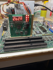
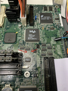
I have this socket 7 motherboard that won't post. No Video. No Beeps... Power works. Reset works. Voltages seem good. POST card hangs at 2B.

What I know about the Motherboard:
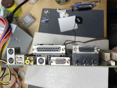
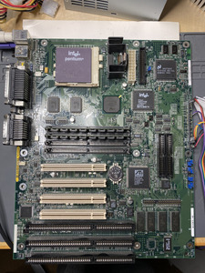
ATX form factor
Socket 7 with a Pentium 133 installed
32mb of 72 pin ram installed
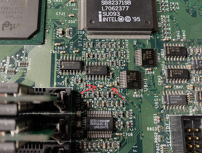
Intel 430HX Chipset
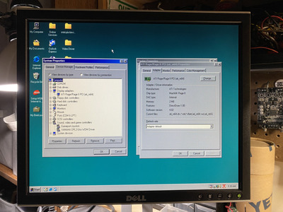
Onboard ATI Rage II graphics
Onboard Yamaha OPL sound
Intel E28F002 bios chip

E139761 Printed in-between the ISA slots
PB 653140-004 printed on the underside (PB for Packard Bell?)

It would be great to get this board identified if possible.

The board is clean and looks in good condition. I've not found any scratches, corrosion, or damaged components. The onboard chips like the chipsets cache gpu and bios get warm to the touch but not hot. I don't think anything is shorted.

I'm not sure where to go from here. Any advice to further troubleshoot this board would be greatly appreciated. Am I missing something simple? I'm no expert and pretty new to retro PCs. I'm a competent solderer with a basic knowledge of electronics.

Many thanks in advance!!!

Attachments

  • IMG_2736.jpeg
    Filename
    IMG_2736.jpeg
    File size
    1.27 MiB
    Views
    600 views
    File license
    Public domain
  • IMG_2735.jpeg
    Filename
    IMG_2735.jpeg
    File size
    1.67 MiB
    Views
    600 views
    File license
    Public domain
  • IMG_2743.jpeg
    Filename
    IMG_2743.jpeg
    File size
    712.51 KiB
    Views
    600 views
    File license
    Public domain
Last edited by Proto-Schlock on 2024-03-25, 11:33. Edited 1 time in total.

Reply 2 of 17, by Proto-Schlock

User metadata
Rank Newbie
Rank
Newbie

Thanks so much!!

How'd you find the board on theretroweb? I tried to search for it but was unsuccessful.

I can double check the jumpers but I think they're good. The jumper settings are printed on the motherboard so I could set them without the manual.

Thanks again,

Reply 3 of 17, by majestyk

User metadata
Rank Oldbie
Rank
Oldbie

Have you tried jumpering the "VRE" jumper (J8L1) to default 1-2? (It´s 2-3 in the picture)

If you have a multimeter check the voltage at the output pin of the VRM transistor.
I have a similar Intel HX mainboard and I remember it´s quite picky about RAM. Did you try different sets of RAM sticks?

Reply 4 of 17, by Proto-Schlock

User metadata
Rank Newbie
Rank
Newbie

Yea I've tried both VRE and O/D. Still no POST. Is it odd that that is the only way to adjust the CPU voltage? I get about 3.5v from the CPU power pins in VRE mode and 3.4V in O/D.

Reply 5 of 17, by Proto-Schlock

User metadata
Rank Newbie
Rank
Newbie

I've tried about five different sets of ram already ranging from 8mb to 64mb. They all seem to behave the same. With no ram I get (E1,E0) on the POST card. With any ram I install I get (2b,2a). What Ram worked for you?

Reply 7 of 17, by Proto-Schlock

User metadata
Rank Newbie
Rank
Newbie

I don't have a PCI or ISA video card at the moment. I could pick one up for cheap for testing purposes. It may solve the problem but I have doubts. You'd think id get a POST beep at least without an add-on GPU given the board has a builtin one.

Having said that, I'm feeling like I'm dealing with an I/O issue. Do boards like these need to see a FDD to boot?

Reply 8 of 17, by zuldan

User metadata
Rank Member
Rank
Member
Proto-Schlock wrote on 2024-03-24, 11:33:

I don't have a PCI or ISA video card at the moment. I could pick one up for cheap for testing purposes. It may solve the problem but I have doubts. You'd think id get a POST beep at least without an add-on GPU given the board has a builtin one.

Having said that, I'm feeling like I'm dealing with an I/O issue. Do boards like these need to see a FDD to boot?

The post code points to something video related. Using a PCI video card may help. I would also check the pins of the ATI chip to make sure they haven’t lost contact with the board.

What’s the voltage on that CR2032? Sometimes weird things can happen during post with a low voltage battery on some motherboards.

Reply 9 of 17, by Proto-Schlock

User metadata
Rank Newbie
Rank
Newbie

Zuldan - How do you know the post code is video related? I haven't found a good lookup for this boards bios.

I did a quick look at the ATI chip. Pins and surrounding SMTs all look firmly attached but worth going over more carefully. I also tried booting while pressing down of the chip - no change.

The CD2032 reads 3.2v but is an older battery. Wouldn't hurt to swap in a new one. I get the same POST code with the battery removed for what it's worth.

Reply 10 of 17, by ciornyi

User metadata
Rank Member
Rank
Member

Im agree with zuldan that its video issue . Btw i couldnt see vga cable connected . Did you connect monitor?

DOS: 166mmx/16mb/Y719/S3virge
DOS/95: PII333/128mb/AWE64/TNT2M64
Win98: P3_900/256mb/SB live/3dfx V3
Win Me: Athlon 1700+/512mb/Audigy2/Geforce 3Ti200
Win XP: E8600/4096mb/SB X-fi/HD6850

Reply 11 of 17, by kaputnik

User metadata
Rank Oldbie
Rank
Oldbie

Sorry if stating the obvious, but have you tried resetting CMOS, in case onboard video can disabled from BIOS, and it's simply a question of the board expecting a graphics card in an expansion slot if so? Or checked if there's some jumper for disabling it?

Also, those post cards can be pretty flaky when used with PCI. Always plugging them in an ISA slot when possible 😀

Reply 12 of 17, by Proto-Schlock

User metadata
Rank Newbie
Rank
Newbie

Update - It's Working!!

Thank you everyone for helping me troubleshoot this board!

Before I found the problem I replaced the CMOS battery with a fresh 2032. This didn't change anything but still worth ruling out. Moving the POST card to the ISA slots produced the same codes (good to know the ISA slots can be more reliable). I then started probing around the board looking for activity or lack of activity. This is when I found a small light scratch and two tiny damaged surface mount capacitors. One partially broken off and the other missing. The partially broken cap wasn't giving me a value reading. I soldered two new .1 caps on the board and it fired up to a SONY boot screen?! Either I guessed the capacitance right or the value isn't super critical.

Anyways, I'm stoked I got it working. The board is running windows98 off a CF card no problem atm!

Thanks again for everyones help!!

P.S. I have two more broken Socket 7 boards I might need more help with 😀

Attachments

  • IMG_2748.jpeg
    Filename
    IMG_2748.jpeg
    File size
    1.9 MiB
    Views
    318 views
    File license
    Public domain
  • IMG_2747.jpeg
    Filename
    IMG_2747.jpeg
    File size
    577.89 KiB
    Views
    318 views
    File license
    Public domain

Reply 13 of 17, by zuldan

User metadata
Rank Member
Rank
Member
Proto-Schlock wrote on 2024-03-25, 11:30:
Update - It's Working!! […]
Show full quote

Update - It's Working!!

Thank you everyone for helping me troubleshoot this board!

Before I found the problem I replaced the CMOS battery with a fresh 2032. This didn't change anything but still worth ruling out. Moving the POST card to the ISA slots produced the same codes (good to know the ISA slots can be more reliable). I then started probing around the board looking for activity or lack of activity. This is when I found a small light scratch and two tiny damaged surface mount capacitors. One partially broken off and the other missing. The partially broken cap wasn't giving me a value reading. I soldered two new .1 caps on the board and it fired up to a SONY boot screen?! Either I guessed the capacitance right or the value isn't super critical.

Anyways, I'm stoked I got it working. The board is running windows98 off a CF card no problem atm!

Thanks again for everyones help!!

P.S. I have two more broken Socket 7 boards I might need more help with 😀

Well done! Another retro motherboard back in action 😀

Reply 14 of 17, by kaputnik

User metadata
Rank Oldbie
Rank
Oldbie
Proto-Schlock wrote on 2024-03-25, 11:30:
Update - It's Working!! […]
Show full quote

Update - It's Working!!

Thank you everyone for helping me troubleshoot this board!

Before I found the problem I replaced the CMOS battery with a fresh 2032. This didn't change anything but still worth ruling out. Moving the POST card to the ISA slots produced the same codes (good to know the ISA slots can be more reliable). I then started probing around the board looking for activity or lack of activity. This is when I found a small light scratch and two tiny damaged surface mount capacitors. One partially broken off and the other missing. The partially broken cap wasn't giving me a value reading. I soldered two new .1 caps on the board and it fired up to a SONY boot screen?! Either I guessed the capacitance right or the value isn't super critical.

Anyways, I'm stoked I got it working. The board is running windows98 off a CF card no problem atm!

Thanks again for everyones help!!

P.S. I have two more broken Socket 7 boards I might need more help with 😀

Probably those caps are used for signal conditioning. They might not be critical for the computer to boot, but wrong values could cause hard to pinpoint anomalies later. I'd try my best to find the correct values if I were you, or at least keep them in mind if the computer - especially the graphics - starts behaving strangely 😀

There were Vaio series desktop computers back in the Pentium MMX days. Maybe the board is from one of those?

Also, good catch, well done getting it back to life 😀

Reply 15 of 17, by majestyk

User metadata
Rank Oldbie
Rank
Oldbie

Looks like the two caps are in the clock generator circuitry, mabe in the output lines. In this case they should be in the pF range like 10 -22 pF. I can´t see it on the picture, but you can have a look at what they are connected to and check the data sheet of the clock-gen - _if_ it´s related.

Reply 16 of 17, by Proto-Schlock

User metadata
Rank Newbie
Rank
Newbie

Here’s a closeup pic of the replaced caps.

The left cap (the right side is ground - the left side goes to the resister below it and maybe branches off somewhere lower on the board). I’m guessing this is a coupling cap?

The Right cap (the left side goes to pin 6 of the 74F08 above it [gate output] - the right side is connected to the cap above it and probably branches other places as well).

Let me know your thoughts on correct values with this info in mind. Thanks!

Attachments

  • IMG_2749.jpeg
    Filename
    IMG_2749.jpeg
    File size
    1.47 MiB
    Views
    213 views
    File license
    Public domain

Reply 17 of 17, by Proto-Schlock

User metadata
Rank Newbie
Rank
Newbie

Final Update:

I tested some different capacitance values with interesting results. To start, I soldered in .1uf caps, because that's what I had on hand. The board actually ran stable, even though this was probably too much capacitance, at least for the right cap I replaced. I've been playing Descent with great results. Game running smoothly and sounding great with the onboard OPL3.

Here's a list of the different caps I tried for the right cap + results:

-10pf - Motherboard would not boot at this value
-100pf - The board booted but seemed to run weirdly fast. Specifically I noticed Descent running inconsistently fast and glitchy. Even at the menu screen the music would start at normal speed then speed up maybe 50% faster.
-1000pf - This value seemed to be the sweet spot, so I'm sticking with it. The motherboard boots up fine and Descent is running normally again.