cross wrote on 2024-04-02, 15:06:Hello momaka, […]
Show full quote
Hello momaka,
Thank you for your reply.
I did actually open a post on eevblog forum,specifically for the PSU: https://www.eevblog.com/forum/repair/atx-psu-ps_on-issue/
Feel free to check it out!
Cool, just did that. Glad to see some pictures.
Caps look visually fine indeed, but I noticed the smaller ones are "CS-logo" branded, which are notorious for going bad.
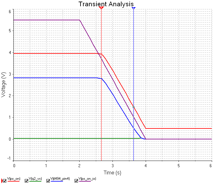
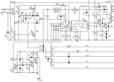
There's a 47 uF 50V small cap right by the secondary heatsink visible in the top-center of the picture. I believe that one should correspond to C25 on the schematic diagram that was posted on EEVLOG by user asis. If so, then that's the filter for the secondary side aux. rail that supplies power to the DBL494 IC. If this cap is bad, the high ripple could cause all sorts of "strange" issues with the IC.
I notice the other caps are the same brand too, so they are really all worth a check if you have an ESR meter. In particular, if the corresponding cap to C31 and C38 on the diagram have failed with high internal leakage current, those can also mess with the logic level perceived as "On" by the IC. So all of the small electros should really be replaced or checked.
Now, you mention you could re-create the problem with playing with resistor combinations on the PS_ON pin. If so, that's indeed a very poor logic level design. Given how copied this design is, I'm curious how many old PSUs with only a 494 / 7500 controller have this issue. Speaking of which, DBL494/TL494 and KA7500 are 100% pin-compatible and interchangeable ICs, so if the DBL494 datasheet is not clear (at least the one I have on my PC seems like an ancient scan from eons ago), you can also reference the KA7500 / KA7500C datasheet.
cross wrote on 2024-04-03, 13:35:Maybe this I can make it clearer like this: […]
Show full quote
Maybe this I can make it clearer like this:
C945 (number 1)
Emitter -> Zener -> Pin 4 on IC
-> 4,7Kohm - Base C945 (number2)
C945 (number 2)
Emitter -> GND
Collector -> Zener -> Pin4
Hmmmm.. are yo sure those Zener diodes are actually such?
Going by the description of your connections above, it is essentially the same thing as the schematic diagram posted by user asis on EEVLOG, except on that schematic, the "Zener" diodes you describe are just standard regular 1N4148 diodes (D24 and D25 to be precise). 1N4148 are usually small, red, glass devices in appearance... which is what perhaps made you confuse them with Zener diodes??
Either way, I'm just trying to confirm here how close your PSU is to the schematic diagram posted.
I also see a 7805 regulator on a heatsink on your pictures, which suggests the 5VSB uses an ancient self-oscillating design with no voltage feedback (open-loop). Ironically, this design is safer compared to the slightly "newer" 2-transistor self-oscillating designs with feedback (presence of an optocoupler next to the 5VSB transformer), since the 7805 regulator has quite the input voltage range before things go haywire. In any case, the presence of the 7805 reg makes the posted schematic diagram one step closer to what your PSU is.
The one main difference I see between the schematic and your PSU is that yours probably uses a linear-regulated 3.3V rail (derived from the 5V rail via MOSFET on the secondary heatsink) rather than a mag-amp regulated 3.3V rail (presence of a 2nd toroid on the output)... unless I missed seeing that 2nd toroid for the 3.3V rail (or perhaps it's a "PI" coil, like on some cheaper older PSUs.) This all relates to the main PSU rails (5V, 12V, 3.3V) and has nothing to do with the PS_ON signal and the PSU half turning On... but again, just mentioning it to have as a comparison to the posted schematic.
...
Anyways, going back to the PS_ON signal pin of your PSU...
If you have a few common spare junk parts around, I ****think**** the easiest circuit fix would be to use a common PNP transistor like 2N3905.
To do so, disconnect PS_ON pin from PSU and connect Emitter of PNP transistor to where the PS_ON pin was. Then connect the Collector of the PNP transistor to ground. Finally, connect a 10k resistor in series with a white or blue LED (green LED may be OK too or might need an extra diode in series) and have this duo connected on one side to PSU's 5VSB and the other to the Base of the PNP transistor. The LED should be forward-biased (Cathode pin) towards the Base of the PNP transistor. Since white/blue (and pink!) LED's have an approximate voltage drop of about 2.7-2.8v minimum (and about 3.3-3.5V nominal), the PNP transistor shouldn't turn On until the voltage at it's base drops to 5V minus the LED voltage drop (i.e. ~3V), so this should bring the PS_ON threshold voltage around 2-2.5V now. You can further lower this by adding in another (regular) diode (so another ~0.6-0.7V drop) to the LED-10k-resistor series connection. Furthermore, the setup with the PNP transistor mentioned above is a bit more of a "all or nothing" when it comes to logic levels. Thus, the invalid "in-between On/Off" state of the PSU should no longer be possible no matter how you mess with the PS_ON signals.
**** I have not built this circuit for this particular use before, so can't 100% confirm it should work as theorized above. But if wired properly, there won't be any danger to the motherboard or the PSU for trying it.
rasz_pl wrote on 2024-04-03, 05:19:Badcaps is more tolerant of wasting money on junk 😀 They have whole section for bad supplies https://www.badcaps.net/forum/troubleshooting … r-supply-design
Well, my views might be biased 😁 , since that used to be my main place to hang around for many years (and still is to a point.)
Not all PSUs are a waste of money/time to attempt to fix. There are sometimes very proprietary stuff that's hard or impossible to find, so the only way to go is to fix the original.
Of course, if you dig a little further back through that section on badcaps, you will find quite a few topics of people fixing & upgrading utter junk ATX PSUs, all just for fun. Actually, there's a good few of those started by yours truly here. 🤣 But like anything else, it can be a fun hobby if you have the "knack" for it.
So with that said, I stand by this:
Deunan wrote on 2024-04-03, 08:44: To each their own I guess