First post, by jnemo2004
Rank
Member
Hello, good afternoon (Zaragoza, Spain)
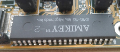
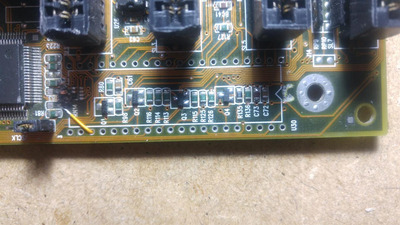
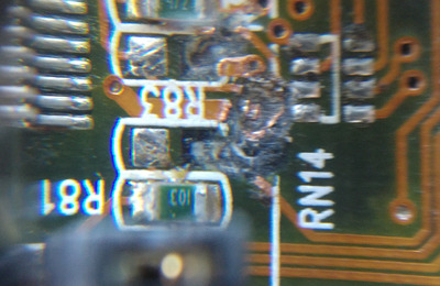
I received the MS-5119 board that someone wanted to remove the KBC, AMIKEY-2 that was soldered on the board with a screwdriver. I actually don't know if I didn't know it couldn't be removed that way or if I just wanted to damage the plate.
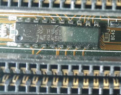
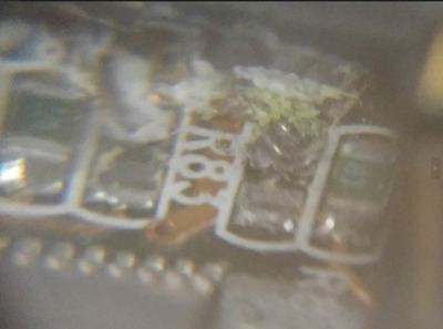
He also did the same with the IC 74F25PC.
The KBC broke two pins and the IC broke it in half.
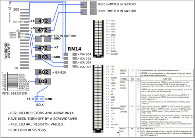
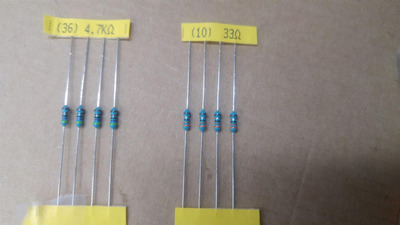
I already have the board ready to solder the removed components but I would need help telling me what resistances I should put in R82 and R83. Also in the RN14 array. From another board I have several arrays of resistance values 102, 122, 122 and 472 but if none of those values work I can solder individual resistors.
Thank you very much for your help. Greetings.