VOGONS


"TRL" CRT Horizontal Position issue

Topic actions

First post, by x86_guy

User metadata
Rank Newbie
Rank
Newbie

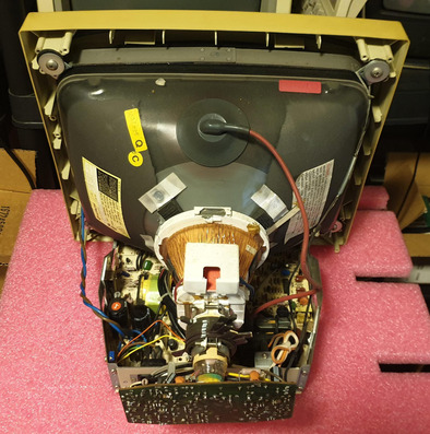
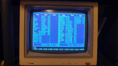
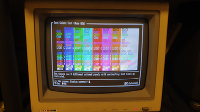
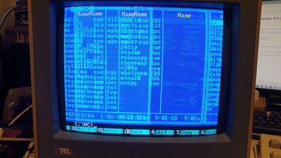
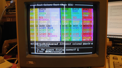
I got an old "TRL" CGA CRT monitor which have a problem with the horizontal positioning.

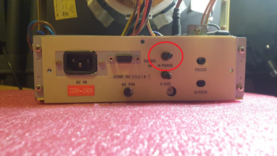
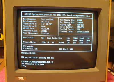
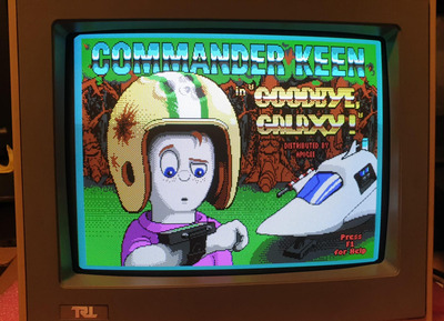
The picture seems to be positioned too much to the right. I tried adjusting the H-phase knob which is accessible at the rear of the monitor, which helped a bit, but the picture is still positioned to the right.

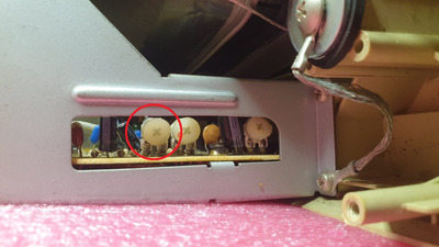
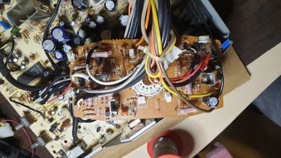
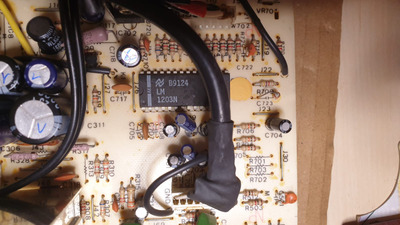
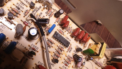
Then, I opened the monitor and adjusted two potentiometers that I found controlling the horizontal positioning also. Again, it helped, but not enough, the picture still positioned way too much to the right.

So, I wanted to try adding resistance to one of the potentiometers (the one that is accessible at the rear) to add some more range, so I added a 50k variable resistor in series to it. This one gave me a bit more of H-positioning range - adjusting it moved the picture more to the left, up to a point where the picture stopped moving, and adding more resistance didn't do anything, so I stopped there.

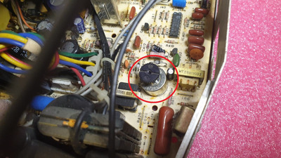
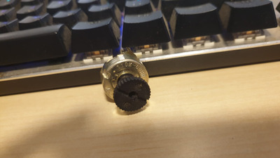
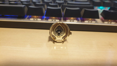
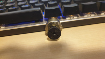
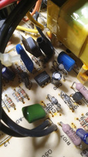
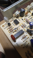
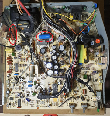
Then, I took a closer look at one of the potentiometers inside the monitor. I took it off to test it.

On it's package written "110K-60HB", and the refdes starts with "VR". Googling it didn't give me any relevant results, so I assumed it's a 110k variable resistor.
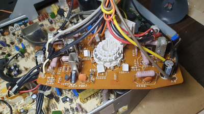
Measuring the total resistance across this component gave me 60ohm, so I assumed something is wrong here. I replaced it with a new 100k variable resistor to see if it make any improvement.

Fired on the monitor with the new variable resistor, and started adjusting it. The pictured seemed to be moving close to the center, but then the component started making smoke - so I turned off the monitor and returned the old one.
I don't really know what went wrong with the replacement - am I wrong with the part identification? Isn't it a 110k variable resistor? or maybe it is - but the resistor I replaced it with, doesn't meet the power spec of the original one (which I don't know because I can't find any info about the original component)?

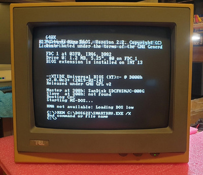
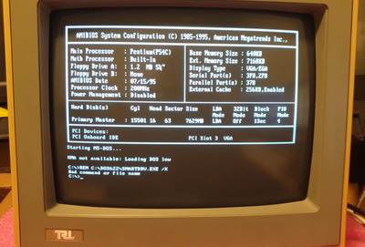
Another weird issue - The font of the test looks really big - It doesn't look like this with another CGA monitor connected to the same PC (it's an XT machine with paradise video adapter configured to CGA mode) - Any idea why is it like this?

Anyone have any thought about this? Any recommendations on how to proceed?

*Attached pictures- I circled in red the parts I mentioned in this post.

Attachments

Reply 1 of 25, by Deunan

User metadata
Rank Oldbie
Rank
Oldbie

Do not mess with the horizontal sweep controls unless you know what you are doing. You are possibly one experiment away from killing HOT and/or the flyback transformer. HOT can be replaced (though it might be costly), the transformer not so much. If enough HV is suddenly produced it could also arc in the tube and damage the gun.

One look at the picture should tell you the vertical linearity is terrible. Now, these monitors are not exactly up to SVGA standards when it comes to linearity in general but one should not really see "scanlines" on the top and compression on the bottom. Most likely some of the electrolytic caps are baked and lost a lot of capacitance, and/or the ESR went up quite a bit. I'd start with that. It'd be great to have service manual or a schematic but a lot can be done even without one, these things are not exactly very complicated.

You can leave the power supply section as-is for now if the picture is bright and there isn't a slow wave (or a dark bar) moving up/down the screen. But any electrolytic capacitor close to anything that produces heat should be tested or just replaced.

Reply 2 of 25, by x86_guy

User metadata
Rank Newbie
Rank
Newbie

Deunan, thanks for the response.

For the vertical linearity - At cold startup it's much worst, than within couple of seconds it's self improving until it gets to a stable point, and looks like in the picture attached. Any idea why?

Anyway, I'll check the capacitors.

Reply 3 of 25, by Deunan

User metadata
Rank Oldbie
Rank
Oldbie
x86_guy wrote on 2024-03-30, 22:41:

For the vertical linearity - At cold startup it's much worst, than within couple of seconds it's self improving until it gets to a stable point, and looks like in the picture attached. Any idea why?

Linearity control is usually a simple RC circuit with limited range (and if the monitor uses ICs rather than transistors there might not even be a need for such control) because there shouldn't be a need to adjust this a lot. So typically in this circuit there aren't any electrolytic caps, and the vertical sweep generator in general should be using stable foil capacitors as well. Any electrolytics there are only to filter the supply voltage - those might be bad, but then I'd expect other issues (compressed or blown out picture, no or unstable vertical sync, etc).

There usually is an electrolytic cap in series with the yoke winding, that one is rather critical. And it will go bad earlier due to pulse operation. There might be another there for the feedback, also important, and yet one more that is actually in the horizontal sweep circuit - this one generates boost voltage (voltage higher than what PSU produces to help with linearity, plus it's a simple way to assure a soft start of the monitor). This particular cap is on the primary side of the flyback and usually located close to it and therefore runs hot. And it gets the horizontal pulses plus any spikes produced by the transformer, so this one is usually the very first capacitor to degrade. This particular electrolytic is best replaced with 105C low-ESR variant, but any modern good quality replacement (85C standard ESR) will work fine as well.

TL;DR: I don't like replacing electrolytic capacitors and calling it a repair but in this case it's what you should do if you have no means of testing the caps in circuit.

Reply 4 of 25, by x86_guy

User metadata
Rank Newbie
Rank
Newbie

I checked most of the capacitors for capacitance and ESR with a capacitor tester - The results are good. I might procced the test if I won't find any other solution for the problems.

For the potentiometer I talked about earlier, which controls the horizontal position and have the stamp "110K-60HB" (you can see a picture of it in my first post):
Any clarification what is this component? Is it a variable resistor?
If it is, (which is probably is, because it got the a refdes starts in "VR") - I would expect 110k resistance across the far terminals, but I get max of 60 ohms.
I couldn't find this component on the net, and trying to replace it with another 110k variable resistor set it on smoke (as I mentioned on the first post).

Reply 5 of 25, by Deunan

User metadata
Rank Oldbie
Rank
Oldbie
x86_guy wrote on 2024-04-03, 19:09:

For the potentiometer I talked about earlier, which controls the horizontal position and have the stamp "110K-60HB" (you can see a picture of it in my first post):
Any clarification what is this component? Is it a variable resistor?

It looks like one but I find the markings equally confusing. Perhaps the 60HB is meant to say it's 60 ohms, although it's a rather low value. Then again 110k is also kinda high - I would expect something in kiloohms range.
It could be a wire-wound potentiometer that's somewhere near the final output stage of the horizontal drive, that would explain the value, but I've never seen such setup in a PC monitor. Where exactly did you pull it out of? It's not one of the back side pots, the shaft is different.

Some more photos would help. Of the PCB and monitor in general, of the pot (I think I see some more markings on it). You've never said if it's a color or mono monitor, I assumed mono based on the wiring but I could be wrong. Does it actually say CGA anywhere on the monitor?
Note, there usually is a coil in series with the horizontal section of the yoke, it's there to control width but also affects horizontal linearity and position too. Please do not mess with it until you rule out every other cause - these coils are not accessible from outside and never change value unless they short somehow (and that is very rare on modern monitors).

I would still try to resolve the vertical linearity problem first. It's obviously very bad and shouldn't be. When fixing CRT monitors or TVs you first want to have a nice, even raster and only then you can start tweaking it to fill the screen properly.

Reply 6 of 25, by x86_guy

User metadata
Rank Newbie
Rank
Newbie

Attached more photos to this post.
And the board, you can see capacitors marked with "V", those are the ones I tested so far (successfully).

This is a color monitor, and I assume it's CGA because pin 2 is shorted to GND (on EGA this pin is "Red 0" signal). It also works fine in CGA mode, while configuring my paradise video card to EGA mode on this monitor, makes it loose sync.

For the vertical linearity problem, I'll be happy to fix it but I don't really know how to proceed. I may continue testing the capacitors, any other ideas?

Thanks!

Attachments

Last edited by x86_guy on 2024-04-03, 22:40. Edited 1 time in total.

Reply 7 of 25, by x86_guy

User metadata
Rank Newbie
Rank
Newbie

Attached more photos of the potentiometer and also the small board of the tube.

Attachments

Reply 8 of 25, by Deunan

User metadata
Rank Oldbie
Rank
Oldbie

So it is a wire-wound pot. It can't be 110k, the wire is too thick and there's not enough of it to get such high resistance. So it's a 60 ohm, as the second part of the markings state - those very rarely go bad. Such a low value, heavy duty potentiometer could even be in series with the yoke coil, and it'll get nasty high voltage spikes on it (on top of the high current). It won't damage this pot but could easily cause a smaller carbon track pot to smoke.

I'm not familiar with TDA2595, I need to look for some schematics. It doesn't seem like this chip is doing vertical all by itself but it does sync separation so I want to see what kind of circuit would be used with it to make up a full vertical oscillator and driver. Can you write down the marking from other chips? Because of the light angle I can't tell what those are.

As for the caps, good job but you still have quite a few left to test. Do not skip the little ones, in fact some of those can dry out or go open much earlier than the big ones. The ones next to LM1203 are for color (3 channels) so those you can test last, but the lower-left corner of the photo, with 2 chips, that's where you should focus on.

Reply 9 of 25, by Deunan

User metadata
Rank Oldbie
Rank
Oldbie
x86_guy wrote on 2024-04-03, 22:33:

This is a color monitor, and I assume it's CGA because pin 2 is shorted to GND (on EGA this pin is "Red 0" signal). It also works fine in CGA mode, while configuring my paradise video card to EGA mode on this monitor, makes it loose sync.

The reason I asked is because there are some "CGA-compatible" monitors - but not actually for CGA. I think Commodore 1085s is a good example, it's not even compatible as such but has the same kind of DSUB plug IIRC. The 1085s is actually analog RGB, not digitial though (could probably be still used with digitial output when contrast is cranked down, or with additional resistors) and has composite sync input but with ICs there is often enough noise from digital H/V signals picked up to actually generate a pretty stable picture.
Most importantly though that monitor is 50Hz and not 60Hz with different resolution - which might just explain why it would struggle to keep decent linearity even if it could sync, and the horizontal resolution and frequency is close but there might be enough difference (like between CGA and Hercules) to cause a significant horizontal shift in the picture.

TL;DR: If this is not actually CGA monitor but just "compatible" to some extent, esp. if it was meant for 50Hz vertical refresh, then there's nothing wrong with it, simply it wasn't made as multi-sync and won't work with CGA properly. Take that as educated guess for now though.

EDIT: And it turns out LM1203 is actually analog video amp, and the 6 caps on the photo would very nicely match the reference schematic in the datasheet. As far as I can tell from the track layout RGB is fed directly to the chip, not via a resistor divider and certainly not via logic gates that I would expect to see on CGA (if only to make the brown color decode properly). So the theory this is not a CGA but rather some C64/Amiga or something similar monitor got more plausible.

Reply 10 of 25, by x86_guy

User metadata
Rank Newbie
Rank
Newbie

So if I get what you say. this monitor is probably an analog RGB monitor, that somehow accept the signals of the CGA, and it can display the picture but not properly, because it's not supposed to.
Do you have an explanation about how could it actually pick a digital signal if it's not designed for it?
Anyway, even if it's not design for CGA, will I be able to modify it so it will?
I took pictures of the ICs so you can see the P/Ns of each.

Funny thing is, I found over the net a post of someone who got the same monitor, and in the picture he attached you can see the same issue I have (picture positioned too much to the right).
You can see it here: https://forum.vcfed.org/index.php?threads/hel … -monitor.68069/

BTW, do you have an explanation for the big fonts? The weird think is, even when the fonts are so big, all the lines are displayed on the screen (Compared to a standard CGA monitor I got also) .

Attachments

Reply 11 of 25, by Deunan

User metadata
Rank Oldbie
Rank
Oldbie
x86_guy wrote on 2024-04-04, 19:43:

So if I get what you say. this monitor is probably an analog RGB monitor, that somehow accept the signals of the CGA, and it can display the picture but not properly, because it's not supposed to.

Yup, basically that how I see it.

x86_guy wrote on 2024-04-04, 19:43:

Do you have an explanation about how could it actually pick a digital signal if it's not designed for it?

It probably has inputs for separate H/V sync signals, that 74LS86 is a XOR gate chip, quite often used as input amp and polarity changer for the TTL level sync signals. You should try to figure out where pins 6,7,8 and 9 of the input connector go to. My bet is 8 and 9 are connected to the LS86.

Pin 6 not connected at all would tell us this monitor doesn't have intensity input, which would further suggest it's analog RGB. The difference between analog and TTL/digital is not that big - analog accepts any voltage value from a specified range (usualy 0.7V p-p, but 1V and sometimes even 5V are also possible) and digital accepts just 2 states, on and off. But obviously on/off is also some voltage so an analog input will just interpret it as zero and full brightness. There is the problem of signal level and overdriving but as I've said it could perhaps be in range of the contrast control to clamp down. Not sure about long term usage, would the video amp tolerate this or get damaged eventually? Hard to say, it is below absolute max ratings but outside specified input range.

x86_guy wrote on 2024-04-04, 19:43:

Anyway, even if it's not design for CGA, will I be able to modify it so it will?

Not easily. For true CGA you'd need the circuitry to correct brown color, if intensity is not supported then some more logic will be required. It can all be done though with perhaps small extra PCB. The main problem might be the correct scanning frequency, that would require some parts swapping and unless you have some experience with that (I don't) it's rather risky business. We still don't know if the vertical linearity is down to caps (or some other damage) or wrong frequency.

x86_guy wrote on 2024-04-04, 19:43:

I took pictures of the ICs so you can see the P/Ns of each.

K335P is just an optocoupler and I'm still not seeing the vertical deflection IC. I think it might be an integrated oscillator and driver transistor, under that rectangular heatsink. It's frankly the only thing there that could be. It does have vertical linearity pot next to it, I assume you tried tweaking it already?
That thing has an extra capacitor soldered on the bottom side of the PCB. It sure is hot there so do check that one as well, preferably even desolder at least one lead for tesing.

EDIT: Well that 555 could be a vertical oscillator. Rather unusual to use such chip when horizontal deflection is done with a dedicated TV IC, but if it works... If that's the case then the odd looking foil capacitor (right in the corner, with weirdly long leads) would be what sets the frequency, along with a resistor or two nearby. I doubt the cap went bad (not impossible though) but check the soldering for cracks.

x86_guy wrote on 2024-04-04, 19:43:

BTW, do you have an explanation for the big fonts? The weird think is, even when the fonts are so big, all the lines are displayed on the screen (Compared to a standard CGA monitor I got also) .

That might be some sort of screen wrap-around due to wrong frequency. Did you try running some program that displays 40x25 and 80x25 pattern? For 80x25 even something like Norton Commander will do. See how that fits.

EDIT2: You know, rather than keep guessing could you just check the color pattern? Does it do brown properly or not?

Reply 12 of 25, by x86_guy

User metadata
Rank Newbie
Rank
Newbie

Thanks for the detailed explanation.

I made a video test using "checkit" utility of this monitor VS real CGA monitor - The brown there looks like yellow on the TRL monitor, while the CGA monitor displays the brown correctly.
Attached photos of both monitors displaying NC and checkit video test (one of the screens of the test).

BTW, did you see the link I attached in the last post, of the TRL monitor I found on another forum?

Attachments

Reply 13 of 25, by Tiido

User metadata
Rank l33t
Rank
l33t

Yours definitely has a failure in the line deflection part because of the foldover seen. Probably one of the big film capacitors has failed since any change in those will cause change in the raster and HV generation.

T-04YBSC, a new YMF71x based sound card & Official VOGONS thread about it
Newly made 4MB 60ns 30pin SIMMs ~
mida sa loed ? nagunii aru ei saa 😜

Reply 14 of 25, by x86_guy

User metadata
Rank Newbie
Rank
Newbie
Tiido wrote on 2024-04-06, 18:13:

Yours definitely has a failure in the line deflection part because of the foldover seen. Probably one of the big film capacitors has failed since any change in those will cause change in the raster and HV generation.

Those can fail without external physical sign?
I tested the biggest two caps on the board, marked in the photo attached - both seem fine.

Attachments

Reply 15 of 25, by Deunan

User metadata
Rank Oldbie
Rank
Oldbie
x86_guy wrote on 2024-04-06, 20:37:

Those can fail without external physical sign?
I tested the biggest two caps on the board, marked in the photo attached - both seem fine.

Usually not - internal (full or partial) short or open lead can happen to them, especially these particular ones because of the voltage spikes. But the caps you tested are not in deflection waveform generation, those are parts of RC snubber networks - one for vertical and one for horizontal. Those very rarely fail and when they do the power transistors follow shortly after. Failure of these would result in bad linearity but not picture wrapping around this much (and so evenly).

In fact the foldover seems to be in the horizontal direction, you do get 25 lines vertically but only ~40 or so horizontally. And the visible scanlines would suggest the monitor is expecting interlaced signal. This, coupled with lack of brown decoding tells you it's not a CGA monitor then. Yes I did see the other thread but that owner also belived he has a CGA montior and that is clearly not the case, unless there are different models or versions that can't be easily distinguished - that would be a terrible choice on the manufacturer part.

I don't really know which computer would be compatible with such monitor. It needs to be old enough to output 40x25 text instead of 80x25, but apparently it was also TV compatible if the signal is indeed interlaced. So why would anyone use a dedicated monitor instead of a TV then? And what about V/H sync, it seems to like the separate signals on pin 8 & 9 (Did you try to trace where those go? To the LS86?). Not sure about analog/digital but clearly this monitor can take digital and has the dynamic range on the video amp to not saturate. Perhaps it can be considered "universal" then, to some extent at the very least. One thing it can't do is CGA intensity bit, that's visible in the photos.

All in all the monitor seems to work fine and is pretty clean inside (unless you cleaned it?) so hasn't seen that much use. The tube could be still pretty strong. As I've mentioned the mod to CGA would not be trivial and a bit risky to the flyback, since that thing is mant to operate at specific frequency with little room for tweaking. Don't trash it though, chances are it's a rare thing for some old machine and someone would pay good money for a monitor with a strong CRT. If only somebody can figure out what kind of computer it would work with 😀

EDIT: On second thought this is not TV-like because the horizontal frequency would need to double to get the raster in order. So it might be 31kHz / 60Hz (or 50Hz, or can be dual mode) that just happens to sync to the CGA at half rate. But still interlated. I know very little about Amigas but I think those could generate something like this?

EDIT2: It's late and I'm tired so these edits are just random thoughts. If this was 31kHz monitor it should be cutting the horizontal lines early, not let them wrap. But perhaps it has such a wide range of horizontal frequencies that it still syncs, kind of, to 15KHz. Well such a mismatch would easily explain why the picture can't be centered, the sync signals are completly out of spec - wrong time, wrong width. Might not be interlaced either then.

Reply 16 of 25, by Deunan

User metadata
Rank Oldbie
Rank
Oldbie

After looking at the photos with fresh eyes the monitor does indeed cut the lines early, the picture is actually pretty well centered. So what I would do now is connect this to a VGA card - you'll need to make an adapter or just try with some wires (but long wires will introduce a lot of crosstalk and RF noise). Note there are some weird 9-pin VGA devices but the pinout is different, do not use those as reference. You want a cross between standard 15-pin VGA output and 9-pin CGA input - connect pins 1,2 (GND), 3,4,5 (RGB) and 8,9 (H/V sync) on the CGA side to the VGA plug.

Note this might produce werid results because VGA uses different polarity, and changes it too for the text mode (720x400) and the usual 640x480 video mode. Plus the text mode is actually 70Hz. You might want to prepare some testing software in advance and try to run in without keyboard input in case the display is unreadable. But you should test both since going from positive polarity on CGA to negative on VGA might fix the vertical linearity and horizontal centering range. I would expect at least the 640x480 graphics mode to show stable picture.

Reply 17 of 25, by x86_guy

User metadata
Rank Newbie
Rank
Newbie

It looks like the H & V signals going to the "74LS86".
I cleaned the monitor inside, but it was really clean even before. It was probably not seen a lot of use and kept well in the storage.

So I went ahead with your suggestion and prepared an adapter cable of DB15 (male) to DB9 (male) using cat5 cable in-between and used the standard pinout of each.
I was pretty surprised to see the monitor working well connected to a VGA card!!
The picture looking great, the colors are good. I played a bit with the adjustments and now the image is well centered, stretched and focused.

So it is a success!
Can we declare the monitor as VGA monitor, or is it possible it can be compatible with other interface?

Funny thing is, I have another monitor which is VGA but with DB9 connector. But this one didn't show an image when it was connected to a CGA/EGA video card, just un-synced something. I was able to figure it's a VGA because I found the manual of it, and there was also the pinout (different than the TRL, not standard) so I could make an adapter for it easily. It's a Samsung SyncMaster 3.

The issue now - at cold startup the image is vertically shrunk and vertical linearity isn't ok. Those issues self sorted after a minute or so of the monitor running - Any directions?

Thanks a lot for the professional help, really appreciated.

Attached pics of the monitor display at cold startup & after warm-up, DB9 to DB15 adapter cable & pinout.

Attachments

Reply 18 of 25, by Tiido

User metadata
Rank l33t
Rank
l33t

Hahahah, wow, this monitor made a really valiant effort to show a low resolution source then, now that it is found out it is a VGA monitor instead.

T-04YBSC, a new YMF71x based sound card & Official VOGONS thread about it
Newly made 4MB 60ns 30pin SIMMs ~
mida sa loed ? nagunii aru ei saa 😜