VOGONS


First post, by tsalat

User metadata
Rank Newbie
Rank
Newbie

Hi everyone,

I have a problem with a new board I bought, and it is mostly my fault this time, 🙁. To explain what happened and what issue I am facing.

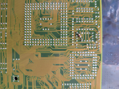
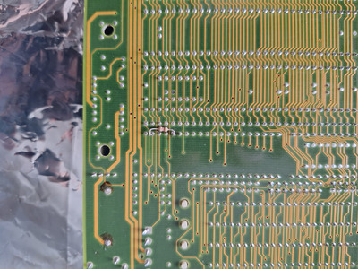
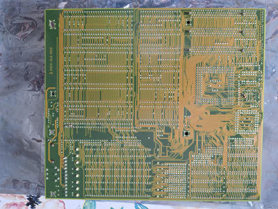
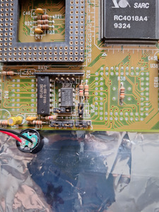
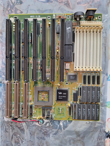
I found a PCChips M601 ver. 1.3B with 4x1MB memory and am486 DX2-66 CPU for a very good price, and of course bought it. Without much thinking, I quickly checked the jumpers and tested the board, no post but something on the debug card at least. I have found some loose legs on the chipset, fixed that, and got the board to post. I could not boot in to the DOS, some strange issues, but okay. I started to look at the board more closely and found some "resistor jumpers" at the bottom of the board, custom made: one next to the keyboard controller and one next to the clock generator. During my fiddling, I have got a small coil of tin beneath the board, next to the keyboard controller and bios area. The area got hot like hell although the board started to post. I have shut it down, realized my mistake, swear a bit, and the board got silent from that moment. Stupid mistake but okay, can happen.

At first:
1| The CPU is 3.3V although the board can feed it only with 5V, I am surprised about this but the CPU is still working - tested it outside with another board.
2| The BIOS was fried, I have changed it but with no change.
3| The debug card is fried, luckily just this card, it is not showing any digits anymore, just -. Tested it outside with several boards, no response - ordered new ones.
4| The keyboard controller is not working with other boards - I would assume these are interchangeable, so I assume it is fried.
5| The memory is fine as well, luckily.
6| The clock generator is set very strangely and the JP7 has 4pins although it should have only 3pins.

I would like to try to analyze it at least but I am confused about the custom parts mentioned above and I would like to revert them.

Questions:
1| Clock generator: I could not find much documentation about the clock generator but according to https://theretroweb.com/motherboards/s/pcchips-m601-ver-1-3b, there should be another one TK9207/TK9307. I could not find anything about this as well not a replacement for it. Can anyone suggest an 8pin clock generator with 33/40MHz output? Or anything suitable I could use.
2| Keyboard controller: I need to get another keyboard controller but by quickly searching on ebay i could not find any with reasonable shipping. Can the clock generator be programmed? If yes, can anyone suggest a suitable IC? Or can anyone suggest if maybe this one could be used - https://bb-elmix.tumblr.com/image/662971873440743424 . Does anyone have an idea why the resistor was at the keyboard controller?

thank you, any idea would be appreciated. I need to wait for the debug cards to move on but still I would like to prepare myself to change stuff or modify before that.

thank you, Tomas

Attachments

Reply 1 of 7, by tsalat

User metadata
Rank Newbie
Rank
Newbie

Hi,

I have realized that I have some clock generators that were fitting in the board, and one of them is the AV9107 - seems to fit the manual as well. I have removed the PLL IC that was there and replaced with the clock generator. The CPU clk is working but with no response from the board. I got the new debug card, and keyboard BIOS as well, still no response. I have tried it with Cyrix DX2 80MHz although I have read that it will accept CPU up to 66MHz - not sure if the issue could be here.

anyway, I will try some more stuff with the board but if anyone has any suggestion, let me know.

thank you, tomas

Reply 2 of 7, by Namrok

User metadata
Rank Oldbie
Rank
Oldbie

I can't really help you, but best of luck with that board. I have an Amptron DX-6600 which I'm lead to believe is merely a rebranding of that exact same board, although perhaps not the same revision. It's a solidly OK board once I got it tuned to the best of my abilities with AMISETUP. Got solidly average results in most benchmarks with a 486 DX2. I suppose most importantly, it just worked with a no-name VLB io multicard, VLB VGA card and an ES1868 sound card. A feat I was marginally surprised by.

Win95/DOS 7.1 - P233 MMX (@2.5 x 100 FSB), Diamond Viper V330 AGP, SB16 CT2800
Win98 - K6-2+ 500, GF2 MX, SB AWE 64 CT4500, SBLive CT4780
Win98 - Pentium III 1000, GF2 GTS, SBLive CT4760
WinXP - Athlon 64 3200+, GF 7800 GS, Audigy 2 ZS

Reply 3 of 7, by tsalat

User metadata
Rank Newbie
Rank
Newbie
Namrok wrote on 2024-04-12, 15:10:

I can't really help you, but best of luck with that board. I have an Amptron DX-6600 which I'm lead to believe is merely a rebranding of that exact same board, although perhaps not the same revision. It's a solidly OK board once I got it tuned to the best of my abilities with AMISETUP. Got solidly average results in most benchmarks with a 486 DX2. I suppose most importantly, it just worked with a no-name VLB io multicard, VLB VGA card and an ES1868 sound card. A feat I was marginally surprised by.

thank you for your answer. I am still angry on myself for damaging the board out of carelessness, I am always placing spacers on the boards but this time I was just too keen to test it and got the tin beneath it.
I have tried different CPU, bellow 66MHz, still no post or beep.
I have replaced the keyboard BIOS a few times with known good ones, still no response - I can try to replace the BIOS once more, I have saved the original ROM before I have fried the original BIOS, luckily.
Since the BIOS and Keyboard BIOS got fried together with the DEBUG card in the ISA slot I know that the tin and short was in the area but I am afraid the chipset got some damage as well in this case.

I am not sure what else to try or what to test to verify the chipset for example, could not find any datasheet to it.
The original "mod" that was there was at the keyboard controller, an resistor was between the VDD and Xin, if the pinout is the same as for W83C42. I have no idea why it was done like this. PIN 2-5 on the IC.

At this moment I need either some suggestions what to try to measure while I know that the area around the ROMs was exposed to the short or the same board to compare the results between each other.
I see that the X1 OSC next to the ISA port is not outputting 32kHz, the HEX inverter near to it has the 32KHz, however, I would expect to measure this frequency on the legs of the OSC as well. I have ordered a new HEX inverter to see if that will help, and then I will change the OSC as well if not - I guess this would work without CPU, right?

I have a few boards left to inspect and maybe fix but this one is bothering me at most 😀.

thx, tomas

Reply 4 of 7, by tsalat

User metadata
Rank Newbie
Rank
Newbie

I have replaced the 32kHz OSC but getting strange output on the legs (one nothing, second 40kHz sin) but 32kHz on the HEX converter, not sure if that is okay. I will wait for the HEX replacement but I do not think that would be the main issue.
Still hopping to find the cause at least...

tomas

Reply 5 of 7, by tsalat

User metadata
Rank Newbie
Rank
Newbie

Hi,

one small update, I have checked the ISA slot, according to the pinout here: https://upload.wikimedia.org/wikipedia/common … SA_Bus_pins.svg.
I have measured a very low resistance between ground and pin A8 (Data 1), and D 01 (MEM CS 16) and ground of about 3 ohm. The D 01 is going straight to the chipset from what I have seen. I have compared this to other 486 board I have near me, and the resistance is higher. This seems to me as a problem with the chipset at the end, correct? Now, someone with the same board would be much of a help to compare the results.

Anyway, what do you think? Any chance to get this chipset from somewhere or replace with something else?

Reply 6 of 7, by tsalat

User metadata
Rank Newbie
Rank
Newbie

The data line seems to be connected to a resistor array A103G, 10pin.
The resistivity is 10K and 22R (the Data 1 line). Could be one pin on the array be shorted?

edit: nope, the resistor array is fine but the Data 1 is definitely shorted.

thx, tomas

Reply 7 of 7, by tsalat

User metadata
Rank Newbie
Rank
Newbie

Hi all,

while waiting for the 50MHz OSC for the DTK board I was looking at this "sad pile" once more and tried to backtrace the DATA 1 PIN from the ISA slot that seems to be shorted and shows below 3ohms against GND.
I have backtraced the traces that are connected to the D1 PIN and found a direct connection to the: Chipset, KBC PIN 13 (D1) and Resistor Array - could be more but I was not able to find any. The 3ohm reading is present with or without the KBC and RA, and thus I am left with the chipset. I would guess that if the chipset would be shorted it would be dead but the surrounding the Data pins are showing activity on the scope. I am not able to find any component that could be shorted to the GND. I though to maybe de-solder this one leg form the board of the chipset to see if the short is still present or no. Not sure how to proceed now, any suggestion or thoughts?

Also, I have taken out the HEX inverter TC4069UBP which sits between the first and second ISA slot, add a socket there after. During continuity measurement I have noticed that between pins O6 - I5 is continuity (blue line) but I am not sure if it could be or not on purpose. It is present with the IC or without the IC. I do not want to de-solder the socket out to examine the area if there could be something causing the short, and thus wanted to ask what you think.

br, Tomas

Attachments