VOGONS


First post, by hbsoftware

User metadata
Rank Newbie
Rank
Newbie

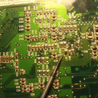
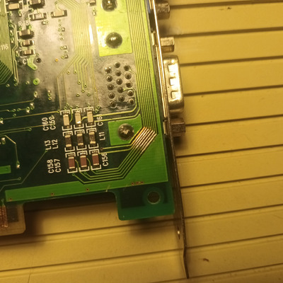
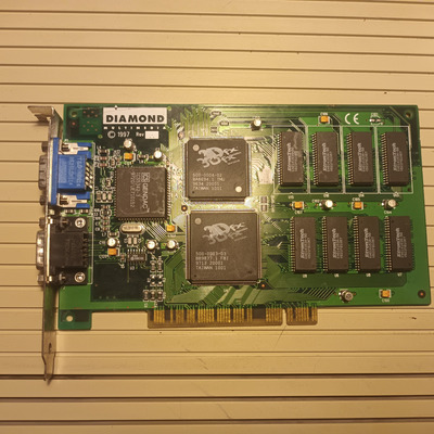
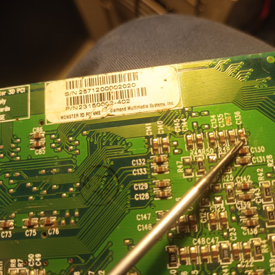
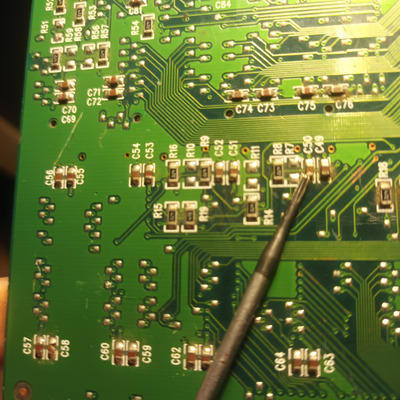
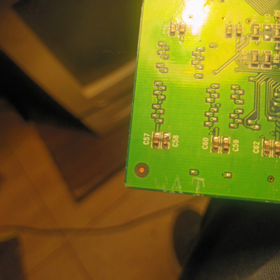
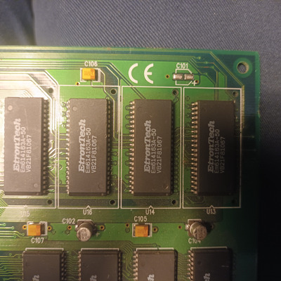
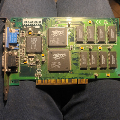
I salvaged this card from the junkyard, it was buried in a bigbag full of cards... on the front its missing a capacitor c101 but its easy to see from the pitch of the pads that its an electrolytic..99% sure its 10uf 16v .. now on the back things are worse...there are bad traces that i will fix , but the worse is that:
C50 and c57 are broken... L10 inductor is broken ...c136 slso broken... i searched for a schematic but no luck... can anyone guide me on to guesstimating some values for these parts??

20240401_165033.jpg
Filename
20240401_165033.jpg
File size
1.2 MiB
Views
466 views
File license
Public domain
20240401_165019.jpg
Filename
20240401_165019.jpg
File size
1.29 MiB
Views
466 views
File license
Public domain
20240401_164944.jpg
Filename
20240401_164944.jpg
File size
1.21 MiB
Views
466 views
File license
Public domain
20240401_164753.jpg
Filename
20240401_164753.jpg
File size
1.64 MiB
Views
466 views
File license
Public domain
20240401_164741.jpg
Filename
20240401_164741.jpg
File size
1.93 MiB
Views
466 views
File license
Public domain
Last edited by hbsoftware on 2024-04-01, 16:12. Edited 2 times in total.

Reply 3 of 13, by butjer1010

User metadata
Rank Member
Rank
Member

I have exact same card as You, can i help somehow, is there any way i can measure those values? Capacitors should not be the problem, i can measure capacitance (not the best tool, but the closest i can measure), but how to measure L10?

Reply 4 of 13, by butjer1010

User metadata
Rank Member
Rank
Member

C136 - 147,5 uf
C50 - 120,2 uf
C57 - 147,1 uf
That was the readings i get from some chinese multimeter. It is not perfect, but very close. For L10 don't know how to help.

Reply 5 of 13, by hbsoftware

User metadata
Rank Newbie
Rank
Newbie
butjer1010 wrote on 2024-04-01, 16:42:

I have exact same card as You, can i help somehow, is there any way i can measure those values? Capacitors should not be the problem, i can measure capacitance (not the best tool, but the closest i can measure), but how to measure L10?

Hi, i dont think the inductor is critical, my worry are the caps..measuring caps in circuit maybe wont work but if you can try i would be very thankfull!!

Reply 6 of 13, by hbsoftware

User metadata
Rank Newbie
Rank
Newbie
butjer1010 wrote on 2024-04-01, 17:01:
C136 - 147,5 uf C50 - 120,2 uf C57 - 147,1 uf That was the readings i get from some chinese multimeter. It is not perfect, but v […]
Show full quote

C136 - 147,5 uf
C50 - 120,2 uf
C57 - 147,1 uf
That was the readings i get from some chinese multimeter. It is not perfect, but very close. For L10 don't know how to help.

Hi, thanks a lot for the effort but unfortunately i dont think they measured ok due to being in circuit, those values are very high and caps had to be huge...i would expect something like 10nf 22nf etc etc not several uf..

Reply 8 of 13, by kingcake

User metadata
Rank Oldbie
Rank
Oldbie
butjer1010 wrote on 2024-04-01, 17:01:
C136 - 147,5 uf C50 - 120,2 uf C57 - 147,1 uf That was the readings i get from some chinese multimeter. It is not perfect, but v […]
Show full quote

C136 - 147,5 uf
C50 - 120,2 uf
C57 - 147,1 uf
That was the readings i get from some chinese multimeter. It is not perfect, but very close. For L10 don't know how to help.

Multimeters are terrible at measuring capacitance. Even more worthless when in circuit. You need an LCR meter that can do > 10KHz for that sort of thing.

C101 is going to be the same as C102. The inductor is almost 100% just a ferrite bead. While they do have different specs, it's probably not critical.

Reply 9 of 13, by butjer1010

User metadata
Rank Member
Rank
Member
hbsoftware wrote on 2024-04-01, 20:24:
butjer1010 wrote on 2024-04-01, 16:42:

I have exact same card as You, can i help somehow, is there any way i can measure those values? Capacitors should not be the problem, i can measure capacitance (not the best tool, but the closest i can measure), but how to measure L10?

Hi, i dont think the inductor is critical, my worry are the caps..measuring caps in circuit maybe wont work but if you can try i would be very thankfull!!

I have always measured the electrolytic caps with this multimeter, and it was always very close with reading, so i thought it would do some good, but Yes, they are in circuit, probably this measurement was worthless. 🙁

Reply 10 of 13, by Joakim

User metadata
Rank Oldbie
Rank
Oldbie
hbsoftware wrote on 2024-04-01, 20:28:
Joakim wrote on 2024-04-01, 16:25:

Here is the thread you are looking for I think.

Voodoo 2 component map

Edit now i see it's not a V2. Woops.

Thanks anyway...any ideas?

I would guess there are not a terribly large amount of different caps on the board. Maybe you can look at a picture of a working card and guess a similar cap. Pick out the similar cap, desolder and measure that with a capacitance meter. You can build a simple Arduino circuit for this.

Of course if would be safer to do this on a fully populated card so depends on if you are willing to risk it. But it is a lot to ask of someone else to do this I suppose, even if it is for science. 😀

Reply 11 of 13, by hbsoftware

User metadata
Rank Newbie
Rank
Newbie

[quote=Joakim post_id=1248820 time=1711988703
[/quote]

I would guess there are not a terribly large amount of different caps on the board. Maybe you can look at a picture of a working card and guess a similar cap. Pick out the similar cap, desolder and measure that with a capacitance meter. You can build a simple Arduino circuit for this.

Of course if would be safer to do this on a fully populated card so depends on if you are willing to risk it. But it is a lot to ask of someone else to do this I suppose, even if it is for science. 😀
[/quote]
I noticed by opening a high res picture of this card that i found online, that there are ceramic caps on the board that are more brown and others more yellow, basically its 3 shades.. so i will dessolder and measure them with the chinese mtester..its very good for small capacitors and fairly precise...if they are decoupling caps i guess i can be wrong and the card still work

Reply 12 of 13, by H3nrik V!

User metadata
Rank Oldbie
Rank
Oldbie

If they're decoupling caps, chances are that it might even work without them 😉

Please use the "quote" option if asking questions to what I write - it will really up the chances of me noticing 😀

Reply 13 of 13, by hbsoftware

User metadata
Rank Newbie
Rank
Newbie

Thanks everyone.
So i washed the board.
Repaired the bad traces and put varnish on the repairs. I found a bent/loose pin on the smaller (top) 3dfx chip, so i straigtened and soldered it...wasnt easy...Bare in mind that i dont have any smd soldering equipment..i have an optical microscope, very old but works great, a regular round tip 30w iron and bunch of tweezers..

I unsoldered 3 caps on random places, from the same size as the ones broken, soldered leads on them ( wasnt fun)and tested them on the chinese mtester...they all measure 10nf.. so i ordered a bunch of them..as said they are probably decoupling and some are in parallell with others. Couldnt find a suitable inductor locally so for testing i will just bridge it.

20240403_232119.jpg
Filename
20240403_232119.jpg
File size
1.38 MiB
Views
137 views
File license
Public domain
20240403_232102.jpg
Filename
20240403_232102.jpg
File size
1.58 MiB
Views
137 views
File license
Public domain