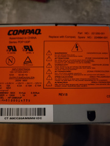
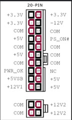
The PSU does appear to have standard output voltages - i.e. 3.3V, 5V, 12V, -5V, -12V, and 5VSB (5VAux). The only non-standard one I see is 3.3VAux... and that could be a problem, if it's going to the wrong pin. (In fact, if this rail is present, we need to get rid of it from the ATX connector, since it can't be used anywhere.)
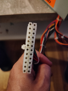
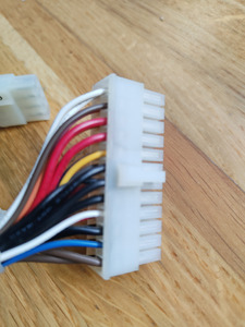
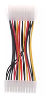
Also, from the two pictures provided above, the color coding on some of the wires definitely doesn't seem to correspond to standard colors. Actually, it's a bit weird here: from the 2nd picture, that side of the connector does appear as if it's wired like a standard ATX connector... except again, the wires don't have standard colors, at the very least. From the 1st picture above, though, none or very few of the wires on that side seem to correspond to their proper locations or colors.
As to whether or not it can be re-wired - that will only be possible if you have the right amount of 3.3V, 5V, 12V, and ground wires... and of course the standard PS_ON, PG (power good), and 5VSB... which still begs the question where (if anywhere) is the 3.3VAux rail?
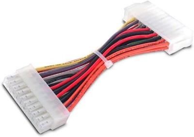
Rather than re-inventing the wheel, perhaps there are PSU adapters sold for this Compaq model (for the PC that is.) Generally these adapters would be to adapt a regular standard ATX PSU to the non-standard ATX format of the motherboard. But since we are doing the reverse, an adapter like that should still work? (Anyone else want to chime in on this?) I'm personally faster with a multimeter and a soldering iron, so if it was mine, I'd just open the PSU, check where each wire connects and re-wire the PSU accordingly.
But you tell us which way you want to proceed. 😉