First post, by Darmok

- Rank
- Newbie
When I needed to control some homemade devices located inside the computer case, I thought about developing some kind of GPIO device. I didn’t want to take up the always missing ISA slot, so I could only use either a COM or LPT port to connect the GPIO. In many cases, connecting to the LPT port inside the computer case is impossible without soldering the wires directly to the connector, at the same time there is access to the pin header of the COM port. Therefore, I implemented the option of connecting the GPIO board to the COM port.
At the moment I use the device to control the Scanliner (Simple DIY scanliner), PC speaker sound device (PC Speaker Sound Device. Need advice.) and to switch the frequency of the clock generator and control the Turbo input of the 386 computer. A total of 5 outputs are used, the inputs are not used.
I decided to publish my development, assuming that it might be of interest to someone else.
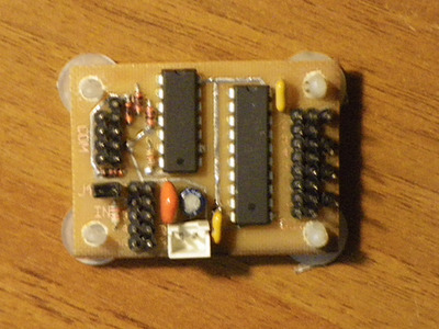
The resulting device turned out to be very simple. It has eight outputs with TTL levels and up to five inputs. In some implementations of the COM port, the DCD and RI lines may not be connected, in which case the number of inputs is reduced to four or three. I believe that manufacturers began to simplify the COM port circuitry after modems died out, but in older systems, as a rule, all port lines are present.
Inputs IN1, IN2, IN3 and IN4 are direct, TRG input can be direct or trigger depending on the setting of jumper J1. Trigger mode allows you to detect the presence of a short pulse at the input between events of reading the input state.
IBM PC compatible computers use a simplified implementation of COM port inputs, so sufficient input signal levels range from +0.6V to +3V, although the inputs are tolerant of levels from -30V to +30V as required by the RS232 standard. Due to the peculiarities of my implementation, the input voltage at the TRG input should not exceed +7V.
All outputs of the GPIO board at the hardware level switch synchronously; if a pause is required between changes in output states, it must be implemented in the control program code.
After a hard or soft reset, the outputs are in the LOW state. This happens due to the fact that after any type of reset, the TXD COM port line also takes on the LOW value. At the same time, during a soft reset, the RTS and DTR lines remain in the same state. Apparently this is a feature of the BIOS code. I don’t presume to say that this will work on all motherboards, but on several tested boards with AWARD BIOS this turned out to be the case.
Some "confusion" in the numbering of outputs on the electrical circuit is due to the design features of the PCB, however, the code provides for easy adaptation to any design.
I have developed a carefully commented control program template code. The code is written in BASIC in the MS PDS7.1 implementation. For clarity, the code is not optimized. Using my code as a basis, the control program is not difficult to implement in any language.
The Russian version is in the gpio_r.zip archive, the English version is in the gpio_e.zip archive.
It is possible to use several control programs, each of which can independently control its own set of outputs. A copy of the output states is stored in the SCR UART register. The TRG input in trigger mode can generally only be used by one program. In order to bypass this limitation in software, it is possible to store states of up to 5 bits in UART registers.
I have also developed a slightly more complex version of the GPIO board (circuitry, PCB and code) that provides 24 outputs and 16 inputs, however I have not prototyped it and therefore have not tested the solution. At the moment I don't have a need for that many inputs/outputs.